Nissan Juke Service and Repair Manual : P0037, P0038 HO2S2 heater
DTC Logic
DTC DETECTION LOGIC

DTC CONFIRMATION PROCEDURE
1.PRECONDITIONING
If DTC Confirmation Procedure has been previously conducted, always perform the following procedure before conducting the next test.
1. Turn ignition switch OFF and wait at least 10 seconds.
2. Turn ignition switch ON.
3. Turn ignition switch OFF and wait at least 10 seconds.
TESTING CONDITION:
Before performing the following procedure, confirm that battery voltage is more
than 11 V at idle.
>> GO TO 2.
2.PERFORM DTC CONFIRMATION PROCEDURE
 With CONSULT-III
1. Turn ignition switch ON and select ŌĆ£DATA MONITORŌĆØ mode of ŌĆ£ENGINEŌĆØ using CONSULT-III.
2. Start engine and warm it up to normal operating temperature.
3. Turn ignition switch OFF and wait at least 10 seconds.
4. Start engine and keep the engine speed between 3,500 and 4,000 rpm for at least 1 minute under no load.
5. Let engine idle for 1 minute.
6. Check 1st trip DTC.
 With GST
Follow the procedure ŌĆ£With CONSULT-IIIŌĆØ above.
Is 1st trip DTC detected? YES >> Proceed to EC-580, "Diagnosis Procedure".
NO >> INSPECTION END
Diagnosis Procedure
1.CHECK HO2S2 POWER SUPPLY CIRCUIT
1. Turn ignition switch OFF.
2. Disconnect heated oxygen sensor 2 (HO2S2) harness connector.
3. Turn ignition switch ON.
4. Check the voltage between HO2S2 harness connector and ground.

Is the inspection result normal? YES >> GO TO 2.
NO >> Repair or replace error-detected parts.
2.CHECK HO2S2 OUTPUT SIGNAL CIRCUIT
1. Turn ignition switch OFF.
2. Disconnect ECM harness connector.
3. Check the continuity between HO2S2 harness connector and ECM harness connector.
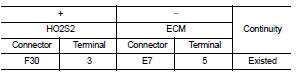
4. Also check harness for short to ground and short to power.
Is the inspection result normal? YES >> GO TO 3.
NO >> Repair or replace error-detected parts.
3.CHECK HEATED OXYGEN SENSOR 2 HEATER
Check the heated oxygen sensor 2 heater. Refer to EC-581, "Component Inspection".
Is the inspection result normal? YES >> Check intermittent incident. Refer to GI-42, "Intermittent Incident".
NO >> GO TO 4.
4.REPLACE HEATED OXYGEN SENSOR 2
Replace heated oxygen sensor 2. Refer to EX-5, "Exploded View".
CAUTION:
ŌĆó Discard any sensor which has been dropped from a height of more than 0.5 m
(19.7 in) onto a hard
surface such as a concrete floor; use a new one.
ŌĆó Before installing new sensor, clean exhaust system threads using Oxygen Sensor Thread Cleaner [commercial service tool (J-43897-18 or J43897-12)] and approved Anti-seize Lubricant (commercial service tool).
>> INSPECTION END
Component Inspection
1.CHECK HEATED OXYGEN SENSOR 2 HEATER
1. Turn ignition switch OFF.
2. Disconnect heated oxygen sensor 2 (HO2S2) harness connector.
3. Check resistance between HO2S2 terminals as per the following.
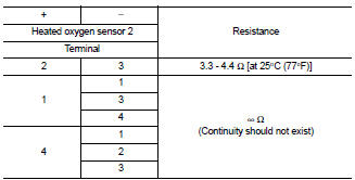
Is the inspection result normal?
YES >> INSPECTION END
NO >> GO TO 2.
2.REPLACE HEATED OXYGEN SENSOR 2
Replace heated oxygen sensor 2. Refer to EX-5, "Exploded View".
CAUTION:
ŌĆó Discard any sensor which has been dropped from a height of more than 0.5 m
(19.7 in) onto a hard
surface such as a concrete floor; use a new one.
ŌĆó Before installing new sensor, clean exhaust system threads using Oxygen Sensor Thread Cleaner [commercial service tool (J-43897-18 or J43897-12)] and approved Anti-seize Lubricant (commercial service tool).
>> INSPECTION END
 P0031, P0032 A/F sensor 1 heater
DTC Logic
DTC DETECTION LOGIC
DTC CONFIRMATION PROCEDURE
1.PRECONDITIONING
If DTC Confirmation Procedure has been previously conducted, always turn
ignition switch OFF and wait wait
at least ...
 P0075 IVT control solenoid valve
DTC Logic
DTC DETECTION LOGIC
DTC CONFIRMATION PROCEDURE
1.PRECONDITIONING
If DTC Confirmation Procedure has been previously conducted, always turn
ignition switch OFF and wait at
least 10 se ...
Other materials:
Precaution Necessary for Steering Wheel Rotation after Battery Disconnect
NOTE:
ŌĆó Before removing and installing any control units, first turn the ignition
switch to the LOCK position, then disconnect
both battery cables.
ŌĆó After finishing work, confirm that all control unit connectors are connected
properly, then re-connect both
battery cables.
ŌĆó Always us ...
Door does not lock/unlock with driver side door lock
knob or door key cylinder
Diagnosis Procedure
1.CHECK POWER DOOR LOCK OPERATION
Check power door lock operation.
Does door lock/unlock with door lock and unlock switch?
YES >> GO TO 2.
NO >> Go to DLK-534, "ALL DOOR : Diagnosis Procedure".
2.CHECK UNLOCK SENSOR
Check unlock sensor.
Refer ...
Rear wheel hub and housing
Exploded View
1. Axle housing
2. Suspension arm
3. Back plate
4. Hub bolt
5. Wheel hub assembly (Bearing-integrated
type)
6. Disc rotor
7. Plug
8. Wheel hub lock nut
9. Cotter pin
: Always replace after every
disassembly.
: N┬Ęm (kg-m, ft-lb)
Removal and Ins
REMOVAL
1. Remove ...
