Nissan Juke Service and Repair Manual : P0031, P0032 A/F sensor 1 heater
DTC Logic
DTC DETECTION LOGIC
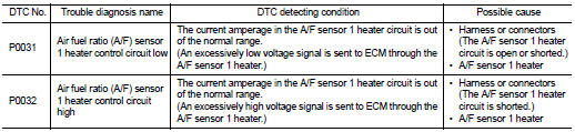
DTC CONFIRMATION PROCEDURE
1.PRECONDITIONING
If DTC Confirmation Procedure has been previously conducted, always turn ignition switch OFF and wait wait at least 10 seconds before conducting the next test.
TESTING CONDITION:
Before performing the following procedure, confirm that battery voltage is
between 10.5 V and 16 V at
idle.
>> GO TO 2.
2.PERFORM DTC CONFIRMATION PROCEDURE
1. Start engine and let it idle for at least 10 seconds.
2. Check 1st trip DTC.
Is 1st trip DTC detected? YES >> Go to EC-577, "Diagnosis Procedure".
NG >> INSPECTION END
Diagnosis Procedure
1.CHECK GROUND CONNECTION
1. Turn ignition switch OFF.
2. Check ground connection E21 and E38. Refer to Ground Inspection in GI-44, "Circuit Inspection".
Is the inspection result normal? YES >> GO TO 2.
NO >> Repair or replace ground connection.
2.CHECK AIR FUEL RATIO (A/F) SENSOR 1 POWER SUPPLY CIRCUIT
1. Disconnect air fuel ratio (A/F) sensor 1 harness connector.
2. Turn ignition switch ON.
3. Check the voltage between A/F sensor 1 harness connector and ground

Is the inspection result normal? YES >> GO TO 4.
NO >> GO TO 3.
3.DETECT MALFUNCTIONING PART
Check the following.
ŌĆó Harness connectors E8, F1
ŌĆó IPDM E/R harness connector E14
ŌĆó 20A fuse (No. 43)
ŌĆó Harness for open or short between A/F sensor 1 and fuse
>> Repair or replace harness or connectors.
4.CHECK A/F SENSOR 1 HEATER OUTPUT SIGNAL CIRCUIT
1. Turn ignition switch OFF.
2. Disconnect ECM harness connector.
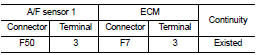
3. Check the continuity between A/F sensor 1 harness connector and ECM harness connector.
4. Also check harness for short to ground and short to power.
Is the inspection result normal? YES >> GO TO 5.
NO >> Repair open circuit, short to ground or short to power in harness or connectors.
5.CHECK A/F SENSOR 1 HEATER
Refer to GI-44, "Circuit Inspection".
Is the inspection result normal? YES >> GO TO 7.
NO >> GO TO 6.
6.REPLACE AIR FUEL RATIO (A/F) SENSOR 1
Replace malfunctioning air fuel ratio (A/F) sensor 1.
CAUTION:
ŌĆó Discard any A/F sensor which has been dropped from a height of more than 0.5 m
(19.7 in) onto a
hard surface such as a concrete floor; use a new one.
ŌĆó Before installing new A/F sensor, clean exhaust system threads using Oxygen Sensor Thread Cleaner (commercial service tool) and approved anti-seize lubricant (commercial service tool).
>> INSPECTION END
7.CHECK INTERMITTENT INCIDENT
Perform GI-42, "Intermittent Incident".
>> Repair or replace
Component Inspection
1.CHECK AIR FUEL RATIO (A/F) SENSOR 1
1. Turn ignition switch OFF.
2. Disconnect A/F sensor 1 harness connector.
3. Check resistance between A/F sensor 1 terminals as follows.

Is the inspection result normal? YES >> INSPECTION END
NO >> GO TO 2.
2.REPLACE AIR FUEL RATIO (A/F) SENSOR 1
Replace malfunctioning air fuel ratio (A/F) sensor 1.
CAUTION:
ŌĆó Discard any air fuel ratio (A/F) sensor which has been dropped from a height
of more than 0.5 m
(19.7 in) onto a hard surface such as a concrete floor; use a new one.
ŌĆó Before installing new air fuel ratio (A/F) sensor, clean exhaust system threads using Heated Oxygen Sensor Thread Cleaner (commercial service tool) and approved anti-seize lubricant (commercial service tool).
>> INSPECTION END
 P0014 EVT control
DTC Logic
DTC DETECTION LOGIC
NOTE:
If DTC P0014 is displayed with DTC P0078, first perform trouble diagnosis for
DTC P0078. Refer to EC-
585, "DTC Logic".
DTC CONFIRMATION PROCEDUR ...
 P0037, P0038 HO2S2 heater
DTC Logic
DTC DETECTION LOGIC
DTC CONFIRMATION PROCEDURE
1.PRECONDITIONING
If DTC Confirmation Procedure has been previously conducted, always perform
the following procedure
before conductin ...
Other materials:
P1642 thermoplunger control unit
DTC Logic
DTC DETECTION LOGIC
Diagnosis Procedure
1.CHECK THERMOPLUNGER CONTROL UNIT POWER SUPPLY CIRCUIT
1. Turn ignition switch OFF.
2. Disconnect thermoplunger control unit harness connector.
3. Check the voltage between thermoplunger control unit harness connector and
ground.
Is the ...
B1234, B1235, B1236, B1237, B1238, B1239 diagnosis sensor unit
DTC Logic
DTC DETECTION LOGIC
DTC CONFIRMATION PROCEDURE
1.CHECK SELF-DIAG RESULT
With CONSULT-III
1. Turn ignition switch ON.
2. Perform ŌĆ£Self Diagnostic ResultŌĆØ mode of ŌĆ£AIR BAGŌĆØ using CONSULT-III.
Without CONSULT-III
1. Turn ignition switch ON.
2. Check the air bag warning la ...
Antenna
To remove the antenna, hold the bottom of the antenna and turn it counterclockwise.
To install the antenna, turn the antenna clockwise and tighten.
CAUTION
ŌĆó To avoid damaging or deforming the antenna, be sure to fold down (if so
equipped) or remove the antenna under the following condition ...
