Nissan Juke Service and Repair Manual : P1642 thermoplunger control unit
DTC Logic
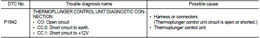
DTC DETECTION LOGIC
Diagnosis Procedure
1.CHECK THERMOPLUNGER CONTROL UNIT POWER SUPPLY CIRCUIT
1. Turn ignition switch OFF.
2. Disconnect thermoplunger control unit harness connector.
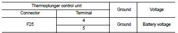
3. Check the voltage between thermoplunger control unit harness connector and ground.
Is the inspection result normal? YES >> GO TO 3.
NO >> GO TO 2.
2.DETECT MALFUNCTIONING PART
Check the following.
• 100A fusible link (letter B) • Harness for open and short between thermoplunger control unit and battery
>> Repair open circuit or short to ground or short to power in harness or connectors.
3.CHECK THERMOPLUNGER CONTROL UNIT GROUND CIRCUIT FOR OPEN AND SHORT
1. Disconnect ECM harness connector.
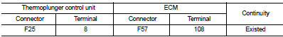
2. Check the continuity between thermoplunger control unit harness connector and ECM harness connector.
3. Also check harness for short to ground and short to power.
Is the inspection result normal? YES >> GO TO 4.
NO >> Repair open circuit or short to ground or short to power in harness or connectors.
4.CHECK INTERMITTENT INCIDENT
Is the inspection result normal? YES >> Replace thermoplunger control unit.
NO >> Repair or replace.
 P1641 thermoplunger control unit
DTC Logic
DTC DETECTION LOGIC
Diagnosis Procedure
1.CHECK THERMOPLUNGER CONTROL UNIT POWER SUPPLY CIRCUIT
1. Turn ignition switch OFF.
2. Disconnect thermoplunger control unit harness connector ...
 P1643 thermoplunger control unit
DTC Logic
DTC DETECTION LOGIC
Diagnosis Procedure
1.CHECK THERMOPLUNGER CONTROL UNIT POWER SUPPLY CIRCUIT
1. Turn ignition switch OFF.
2. Disconnect thermoplunger control unit harness connector ...
Other materials:
High pressure fuel pump and fuel hose
Exploded View
CAUTION:
Never remove or disassemble parts unless instructed as shown in the figure.
1. High pressure fuel pump insulator
2. High pressure fuel pump
3. O-ring
4. Valve lifter
5. Fuel tube assembly
6. Bracket
7. Fuel pump connector protector
8. Fuel feed hose
A. To ce ...
Moving Object Detection (MOD)
CAMERA button (conveniently mounted on the physical display bezel assembly to activate or toggle camera modes)
WARNING
Failure to strictly follow the safety warnings and operational instructions for the correct use of the Moving Object Detection (MOD) ...
NISSAN Intelligent Key
NISSAN Intelligent Key fob (supplied as two complete sets)
Emergency mechanical key (integrated inside the fob)
Key number plate (one unique metal stamp plate)
Your vehicle is protected by advanced security pairing, meaning it can only be ...
