Nissan Juke Service and Repair Manual : P0014 EVT control
DTC Logic
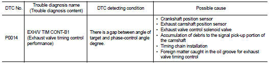
DTC DETECTION LOGIC
NOTE
:
If DTC P0014 is displayed with DTC P0078, first perform trouble diagnosis for
DTC P0078. Refer to EC-
585, "DTC Logic".
DTC CONFIRMATION PROCEDURE
1.PRECONDITIONING
If DTC Confirmation Procedure has been previously conducted, always perform the following procedure before conducting the next test.
1. Turn ignition switch OFF and wait at least 10 seconds.
2. Turn ignition switch ON.
3. Turn ignition switch OFF and wait at least 10 seconds.
TESTING CONDITION:
Before performing the following procedure, confirm that battery voltage is
between 10 V and 16 V at
idle.
>> GO TO 2.
2.PERFORM DTC CONFIRMATION PROCEDURE-I
 With CONSULT-III
1. Turn ignition switch ON and select ÔÇťDATA MONITORÔÇŁ mode of ÔÇťENGINEÔÇŁ using CONSULT-III.
2. Start engine and warm it up to the normal operating temperature.
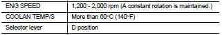
3. Maintain the following conditions for at least 6 consecutive seconds. Hold the accelerator pedal as steady as possible.
4. Let engine idle for 10 seconds.
5. Check 1st trip DTC.
 With GST
Follow the procedure ÔÇťWith CONSULT-IIIÔÇŁ above.
Is 1st trip DTC detected? YES >> Proceed to EC-575, "Diagnosis Procedure" NO >> GO TO 3.
3.PERFORM DTC CONFIRMATION PROCEDURE-II
With CONSULT-III
1. Select ÔÇťDATA MONITORÔÇŁ mode of ÔÇťENGINEÔÇŁ using CONSULT-III.
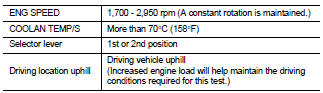
2. Maintain the following conditions for at least 20 consecutive seconds.
CAUTION:
Always drive at a safe speed.
3. Check 1st trip DTC.
 With GST
Follow the procedure ÔÇťWith CONSULT-IIIÔÇŁ above.
Is 1st trip DTC detected? YES >> Proceed to EC-575, "Diagnosis Procedure" NO >> INSPECTION END
Diagnosis Procedure
1.CHECK OIL PRESSURE WARNING LAMP
1. Start engine.
2. Check oil pressure warning lamp and confirm it is not illuminated.
Is oil pressure warning lamp illuminated? YES >> Check the engine oil level. Refer to LU-8, "Inspection".
NO >> GO TO 2.
2.CHECK EXHAUST VALVE TIMING CONTROL SOLENOID VALVE
Check the exhaust valve timing control solenoid valve. Refer to EC-576, "Component Inspection".
Is the inspection result normal? YES >> GO TO 3.
NO >> Replace exhaust valve timing control solenoid valve. Refer to EM-67, "Exploded View".
3.CHECK CRANKSHAFT POSITION SENSOR
Check the crankshaft position sensor. Refer to EC-658, "Component Inspection".
Is the inspection result normal? YES >> GO TO 4.
NO >> Replace crankshaft position sensor. Refer to EM-103, "Exploded View".
4.CHECK EXHAUST CAMSHAFT POSITION SENSOR
Check the exhaust camshaft position sensor. Refer to EC-662, "Component Inspection".
Is the inspection result normal? YES >> GO TO 5.
NO >> Replace exhaust valve timing control position sensor. Refer to EM-78, "Exploded View".
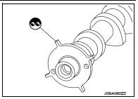
5.CHECK CAMSHAFT (EXHAUST)
Check the following.
ÔÇó Accumulation of debris to the signal plate of camshaft rear end ÔÇó Chipping signal plate of camshaft rear end Is the inspection result normal? YES >> GO TO 6.
NO >> Remove debris and clean the signal plate of camshaft rear end or replace camshaft. Refer to EM-79, "Removal and Installation".
6.CHECK TIMING CHAIN INSTALLATION
Check service records for any recent repairs that may cause timing chain misaligned.
Are there any service records that may cause timing chain misaligned? YES >> Check timing chain installation. Refer to EM-181, "Exploded View".
NO >> GO TO 7.
7.CHECK LUBRICATION CIRCUIT
Refer to EM-200, "Inspection", ÔÇťINSPECTION AFTER INSTALLATIONÔÇŁ.
Is the inspection result normal? YES >> Check intermittent incident. Refer to GI-42, "Intermittent Incident".
NO >> Clean lubrication line.
Component Inspection
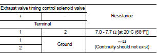
1.CHECK EXHAUST VALVE TIMING CONTROL SOLENOID VALVE-I
1. Turn ignition switch OFF.
2. Disconnect exhaust valve timing control solenoid valve harness connector.
3. Check resistance between exhaust valve timing control solenoid valve terminals as per the following.
Is the inspection result normal? YES >> GO TO 2.
NO >> Replace exhaust valve timing control solenoid valve. Refer to EM-67, "Exploded View".
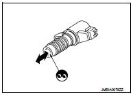
2.CHECK EXHAUST VALVE TIMING CONTROL SOLENOID VALVE-II
1. Remove exhaust valve timing control solenoid valve.
2. Provide 12 V DC between exhaust valve timing control solenoid valve terminals 1 and 2, and then interrupt it. Check that the plunger moves as shown in the figure.
CAUTION:
Do not apply 12 V DC continuously for 5 seconds or more.
Doing so may result in damage to the coil in exhaust valve timing control solenoid valve.
NOTE
:
Always replace O-ring when exhaust valve timing control
solenoid valve is removed.
Is the inspection result normal? YES >> INSPECTION END
NO >> Replace exhaust valve timing control solenoid valve. Refer to EM-67, "Exploded View".
 P0011 IVT control
DTC Logic
DTC DETECTION LOGIC
NOTE:
If DTC P0011 is displayed with DTC P0075, first perform the trouble diagnosis
for DTC P0075. Refer to
EC-583, "DTC Logic".
DTC CONFIRMATION PROCE ...
 P0031, P0032 A/F sensor 1 heater
DTC Logic
DTC DETECTION LOGIC
DTC CONFIRMATION PROCEDURE
1.PRECONDITIONING
If DTC Confirmation Procedure has been previously conducted, always turn
ignition switch OFF and wait wait
at least ...
Other materials:
Precaution
Precaution for Supplemental Restraint System (SRS) "AIR BAG" and "SEAT
BELT
PRE-TENSIONER"
The Supplemental Restraint System such as ÔÇťAIR BAGÔÇŁ and ÔÇťSEAT BELT
PRE-TENSIONERÔÇŁ, used along
with a front seat belt, helps to reduce the risk or severity of injury to the
...
Back door request switch
Component Function Check
1.CHECK FUNCTION
1. Select ÔÇťINTELLIGENT KEYÔÇŁ of ÔÇťBCMÔÇŁ using CONSULT-III.
2. Select ÔÇťREQ SW-BD/TRÔÇŁ in ÔÇťDATA MONITORÔÇŁ mode.
3. Check that the function operates normally according to the following
conditions.
Is the inspection result normal?
YES >&g ...
Rear window defogger does not operate but both door
mirror defoggers operate
Diagnosis Procedure
1.CHECK REAR WINDOW DEFOGGER
Check rear window defogger.
Refer to DEF-31, "Component Function Check".
Is the inspection result normal?
YES >> GO TO 2.
NO >> Repair or replace the malfunctioning parts.
2.CONFIRM THE OPERATION
Confirm the opera ...
