Nissan Juke Service and Repair Manual : P0011 IVT control
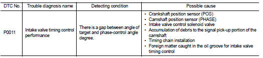
DTC Logic
DTC DETECTION LOGIC
NOTE
:
If DTC P0011 is displayed with DTC P0075, first perform the trouble diagnosis
for DTC P0075. Refer to
EC-583, "DTC Logic".
DTC CONFIRMATION PROCEDURE
1.PRECONDITIONING
If DTC Confirmation Procedure has been previously conducted, always turn ignition switch OFF and wait at least 10 seconds before conducting the next test.
TESTING CONDITION:
Before performing the following procedure, confirm that battery voltage is
between 10 V and 16 V at
idle.
>> GO TO 2.
2.PERFORM DTC CONFIRMATION PROCEDURE-I
 With CONSULT-III
1. Turn ignition switch ON and select “DATA MONITOR” mode with CONSULT-III.
2. Start engine and warm it up to the normal operating temperature.
3. Maintain the following conditions for at least 6 consecutive seconds. Hold the accelerator pedal as steady as possible.
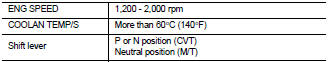
4. Let engine idle for 10 seconds.
5. Check 1st trip DTC.
 With GST
Follow the procedure “With CONSULT-III” above.
Is 1st trip DTC detected? YES >> Go to EC-571, "Diagnosis Procedure" NO >> GO TO 3.
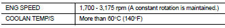
3.PERFORM DTC CONFIRMATION PROCEDURE-II
 With CONSULT-III
1. Maintain the following conditions for at least 20 consecutive seconds.
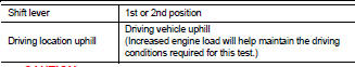
CAUTION:
Always drive at a safe speed.
2. Check 1st trip DTC.
 With GST
Follow the procedure “With CONSULT-III” above.
Is 1st trip DTC detected? YES >> Go to EC-571, "Diagnosis Procedure" NO >> INSPECTION END
Diagnosis Procedure
1.CHECK OIL PRESSURE WARNING LAMP
1. Start engine.
2. Check oil pressure warning lamp and confirm it is not illuminated.
Is oil pressure warning lamp illuminated? YES >> Go to LU-25, "Inspection".
NO >> GO TO 2.
2.CHECK INTAKE VALVE TIMING CONTROL SOLENOID VALVE
Refer to EC-572, "Component Inspection".
Is the inspection result normal? YES >> GO TO 3.
NO >> Replace intake valve timing control solenoid valve.
3.CHECK CRANKSHAFT POSITION SENSOR (POS)
Refer to EC-658, "Component Inspection".
Is the inspection result normal? YES >> GO TO 4.
NO >> Replace crankshaft position sensor (POS).
4.CHECK CAMSHAFT POSITION SENSOR (PHASE)
Refer to EC-662, "Component Inspection".
Is the inspection result normal? YES >> GO TO 5.
NO >> Replace camshaft position sensor (PHASE).
5.CHECK CAMSHAFT (INTAKE)
Check the following.
• Accumulation of debris to the signal plate of camshaft (1) rear end • Chipping signal plate of camshaft rear end
Is the inspection result normal? YES >> GO TO 6.
NO >> Remove debris and clean the signal plate of camshaft rear end or replace camshaft.
6.CHECK TIMING CHAIN INSTALLATION
Check service records for any recent repairs that may cause timing chain misaligned.
Are there any service records that may cause timing chain misaligned? YES >> Check timing chain installation. Refer to EM-181, "Exploded View".
NO >> GO TO 7.
7.CHECK LUBRICATION CIRCUIT
Perform “Inspection of Camshaft Sprocket (INT) Oil Groove”. Refer to EM-200, "Inspection".
Is the inspection result normal? YES >> GO TO 8.
NO >> Clean lubrication line.
8.CHECK INTERMITTENT INCIDENT
Refer to GI-42, "Intermittent Incident".
>> INSPECTION END
Component Inspection
1.CHECK INTAKE VALVE TIMING CONTROL SOLENOID VALVE-I
1. Turn ignition switch OFF.
2. Disconnect intake valve timing control solenoid valve harness connector.
3. Check resistance between intake valve timing control solenoid valve terminals as follows.
Is the inspection result normal? YES >> GO TO 2.
NO >> Replace intake valve timing control solenoid valve.
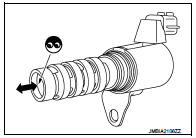
2.CHECK INTAKE VALVE TIMING CONTROL SOLENOID VALVE-II
1. Remove intake valve timing control solenoid valve.
2. Apply 12 V between intake valve timing control solenoid valve terminals 1 and 2, and then interrupt it. Make sure that the plunger moves as shown in the figure.
CAUTION:
Do not apply 12 V continuously for 5 seconds or more.
Doing so may result in damage to the coil in intake valve timing control solenoid valve.
NOTE:
Always replace O-ring when intake valve timing control solenoid valve is removed.
Is the inspection result normal?
YES >> INSPECTION END
NO >> Replace intake valve timing control solenoid valve.
 U1000, U1001 CAN COMM CIRCUIT
Description
CAN (Controller Area Network) is a serial communication line for real time
application. It is an on-vehicle multiplex
communication line with high data communication speed and excellen ...
 P0014 EVT control
DTC Logic
DTC DETECTION LOGIC
NOTE:
If DTC P0014 is displayed with DTC P0078, first perform trouble diagnosis for
DTC P0078. Refer to EC-
585, "DTC Logic".
DTC CONFIRMATION PROCEDUR ...
Other materials:
Periodic maintenance
Periodic Maintenance
The following tables show the normal maintenance schedule. Depending upon
weather and atmospheric conditions,
varying road surfaces, individual driving habits and vehicle usage, additional
or more frequent maintenance
may be required.
Periodic maintenance beyond the la ...
Road test
Description
DESCRIPTION
• The purpose of the test is to determine overall performance of CVT
and analyze causes of problems.
• The road test consists of the following three parts:
1. “Check Before Engine Is Started” TM-190.
2. “Check at Idle” TM-191.
3. “Cruise Test” TM-192.
...
Key warning lamp
Component Function Check
1.CHECK FUNCTION
1. Select “INTELLIGENT KEY” of “BCM” using CONSULT-III.
2. Select “INDICATOR” in “ACTIVE TEST” mode.
3. Check that the function operates normally according to the following
conditions.
Is the inspection result normal?
YES >> K ...
