Nissan Juke Service and Repair Manual : U0415 vehicle speed
Description
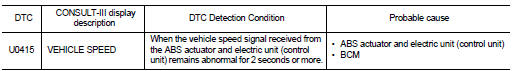
U0415 is displayed if any unusual condition is present in the reception status of the vehicle speed signal from the ABS actuator and electric unit (control unit).
DTC Logic
DTC DETECTION LOGIC
DTC CONFIRMATION PROCEDURE
1.DTC CONFIRMATION
1. Erase the DTC.
2. Turn ignition switch OFF.
3. Perform the ŌĆ£Self Diagnostic ResultŌĆØ of BCM with CONSULT-III, when passed 2 seconds or more after the ignition switch is turned ON.
Is any DTC detected? YES >> Refer to BCS-85, "Diagnosis Procedure".
NO >> INSPECTION END
Diagnosis Procedure
1.ABS ACTUATOR AND ELECTRIC UNIT (CONTROL UNIT) SELF-DIAG RESULTS
Perform ŌĆ£Self-Diagnostic ResultŌĆØ of ABS actuator and electric unit (control unit) with CONSULT-III. Refer to BRC-24, "CONSULT-III Function" (without EPS), BRC-131, "CONSULT-III Function" (with EPS).
Is any DTC detected? YES >> Repair or replace the malfunctioning part.
NO >> Replace BCM. Refer to BCS-93, "Removal and Installation".
 U1010 control unit (can)
DTC Logic
DTC DETECTION LOGIC
Diagnosis Procedure
1.REPLACE BCM
When DTC ŌĆ£U1010ŌĆØ is detected, replace BCM.
>> Replace BCM. Refer to BCS-93, "Removal and Installation". ...
 B2562 low voltage
DTC Logic
DTC DETECTION LOGIC
DTC CONFIRMATION PROCEDURE
1.DTC CONFIRMATION
1. Erase DTC.
2. Turn ignition switch OFF.
3. Perform the ŌĆ£Self Diagnostic ResultŌĆØ of BCM with CONSULT-III, when ...
Other materials:
Camera image signal circuit
Description
ŌĆó The NAVI control unit supplies power to the rear view camera when receiving
a reverse signal.
ŌĆó The rear view camera transmits camera images to the NAVI control unit when
power is supplied from the
NAVI control unit.
Diagnosis Procedure
1.CHECK CONTINUITY CAMERA POWER SUPP ...
B1137 side air bag module LH
DTC Logic
DTC DETECTION LOGIC
DTC CONFIRMATION PROCEDURE
1.CHECK SELF-DIAG RESULT
With CONSULT-III
1. Turn ignition switch ON.
2. Perform ŌĆ£Self Diagnostic ResultŌĆØ mode of ŌĆ£AIR BAGŌĆØ using CONSULT-III.
Without CONSULT-III
1. Turn ignition switch ON.
2. Check the air bag warning la ...
Oil pump fitting bolt
Description
Replace the oil pump fitting bolt and the O-ring if oil leakage or exudes
from the oil pump fitting bol
Exploded View
1. Oil pump fitting bolt
2. O-ring
3. Transaxle assembly
: Always replace after every
disassembly.
: N┬Ęm (kg-m, ft-lb)
: Genuine NISSAN CVT Fluid NS-2
R ...
