Nissan Juke Service and Repair Manual : Camera image signal circuit
Description
• The NAVI control unit supplies power to the rear view camera when receiving a reverse signal.
• The rear view camera transmits camera images to the NAVI control unit when power is supplied from the NAVI control unit.
Diagnosis Procedure
1.CHECK CONTINUITY CAMERA POWER SUPPLY CIRCUIT
1. Turn ignition switch OFF.
2. Disconnect NAVI control unit connector and rear view camera connector.
3. Check continuity between NAVI control unit harness connector and rear view camera harness connector.
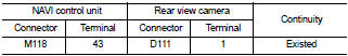
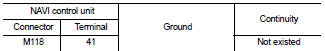
4. Check continuity between NAVI control unit harness connector and ground.
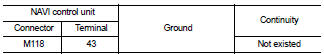
Is inspection result normal? YES >> GO TO 2.
NO >> Repair harness or connector.
2.CHECK VOLTAGE CAMERA POWER SUPPLY
1. Connect NAVI control unit connector and rear view camera connector.
2. Turn ignition switch ON.
3. Shift the selector lever to “R” position.
4. Check voltage between NAVI control unit harness connector and ground.
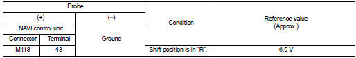
Is inspection result normal? YES >> GO TO 3.
NO >> Replace NAVI control unit. Refer to AV-84, "Removal and Installation".
3.CHECK CONTINUITY CAMERA IMAGE SIGNAL CIRCUIT
1. Turn ignition switch OFF.
2. Disconnect NAVI control unit connector and rear view camera connector.
3. Check continuity between NAVI control unit harness connector and rear view camera harness connector.
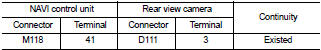
4. Check continuity between NAVI control unit harness connector and ground.
Is inspection result normal? YES >> GO TO 4.
NO >> Repair harness or connector.
4.CHECK CAMERA IMAGE SIGNAL
1. Connect NAVI control unit connector and rear view camera connector.
2. Turn ignition switch ON.
3. Shift the selector lever to “R” position.
4. Check signal between NAVI control unit harness connector and ground.
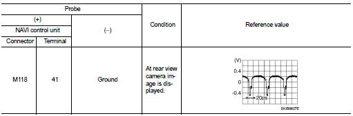
Is inspection result normal? YES >> Replace NAVI control unit. Refer to AV-84, "Removal and Installation".
NO >> Replace rear view camera. Refer to AV-92, "Removal and Installation".
 Microphone signal circuit
Description
Power is supplied from NAVI control unit to microphone. The microphone
transmits the sound voice to the
NAVI control unit.
Diagnosis Procedure
1.CHECK CONTINUITY BETWEEN NAVI CONTROL ...
 Steering switch signal A circuit
Description
Transmits the steering switch signal to NAVI control unit.
Diagnosis Procedure
1.CHECK STEERING SWITCH SIGNAL A CIRCUIT
1. Disconnect NAVI control unit connector and spiral cable conne ...
Other materials:
Excessive operation frequency
Description
ABS function and EBD function operates in excessive operation frequency.
Diagnosis Procedure
1.CHECK BRAKING FORCE
Check brake force using a brake tester.
Is the inspection result normal?
YES >> GO TO 2.
NO >> Check brake system.
2.CHECK FRONT AND REAR AXLE
Che ...
Door mirror remote control switch
Exploded View
1. Instrument lower panel
2. Switch bracket
3. Door mirror remote control switch
Removal and Installation
REMOVAL
1. Remove the instrument lower panel. Refer to IP-13, "Removal and
Installation".
2. Remove mounting screws and remove switch bracket from instrument ...
Engine control system symptoms
Symptom Table
SYSTEM — BASIC ENGINE CONTROL SYSTEM
1 - 6: The numbers refer to the order of inspection.
(continued on next table)
SYSTEM — ENGINE MECHANICAL & OTHER
1 - 6: The numbers refer to the order of inspection ...
