Nissan Juke Service and Repair Manual : Microphone signal circuit
Description
Power is supplied from NAVI control unit to microphone. The microphone transmits the sound voice to the NAVI control unit.
Diagnosis Procedure
1.CHECK CONTINUITY BETWEEN NAVI CONTROL UNIT AND MICROPHONE CIRCUIT
1. Turn ignition switch OFF.
2. Disconnect NAVI control unit connector and microphone connector.
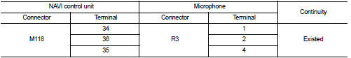
3. Check continuity between NAVI control unit harness connector and microphone harness connector.
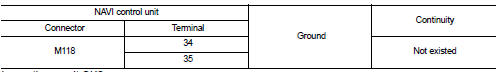
4. Check continuity between NAVI control unit harness connector and ground.
Is inspection result OK? YES >> GO TO 2.
NO >> Repair harness or connector.
2.CHECK VOLTAGE MICROPHONE VCC
1. Connect NAVI control unit connector.
2. Turn ignition switch ON.
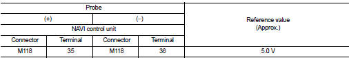
3. Check voltage between NAVI control unit harness connector and ground.
Is inspection result OK? YES >> GO TO 3.
NO >> Replace NAVI control unit. Refer to AV-84, "Removal and Installation".
3.CHECK MICROPHONE SIGNAL
1. Turn ignition switch OFF.
2. Connect microphone connector.
3. Turn ignition switch ON.
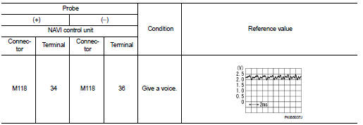
4. Check signal between NAVI control unit harness connector.
Is inspection result OK? YES >> Replace NAVI control unit. Refer to AV-84, "Removal and Installation".
NO >> Replace microphone. Refer to AV-90, "Removal and Installation".
 Power supply and ground circuit
Navi control unit
NAVI CONTROL UNIT : Diagnosis Procedure
1.CHECK FUSE
Check for blown fuses.
Is inspection result OK?
YES >> GO TO 2.
NO >> Be sure to eliminate cause of malfunc ...
 Camera image signal circuit
Description
• The NAVI control unit supplies power to the rear view camera when receiving
a reverse signal.
• The rear view camera transmits camera images to the NAVI control unit when
power ...
Other materials:
Precaution for Supplemental Restraint System
(SRS) "AIR BAG" and "SEAT BELT PRE-TENSIONER"
The Supplemental Restraint System such as “AIR BAG” and “SEAT BELT PRE-TENSIONER”,
used along
with a front seat belt, helps to reduce the risk or severity of injury to the
driver and front passenger for certain
types of collision. This system includes seat belt switch inputs and dual s ...
P0746 pressure control solenoid A
Description
The line pressure solenoid valve regulates the oil pump discharge pressure to
suit the driving condition in
response to a signal sent from the TCM.
DTC Logic
DTC DETECTION LOGIC
DTC CONFIRMATION PROCEDURE
CAUTION:
Always drive vehicle at a safe speed.
NOTE:
If “DTC CONFIRM ...
4WD warning lamp blinks quickly
Description
While driving, 4WD warning lamp blinks 2 times in 1 second and it turns OFF
after 1 minute.
NOTE:
• This symptom protects drivetrain parts when a heavy load is applied to the
electric controlled coupling and
multiple disc clutch temperature increases. Also, optional distribut ...
