Nissan Juke Service and Repair Manual : Steering switch signal A circuit
Description
Transmits the steering switch signal to NAVI control unit.
Diagnosis Procedure
1.CHECK STEERING SWITCH SIGNAL A CIRCUIT
1. Disconnect NAVI control unit connector and spiral cable connector.
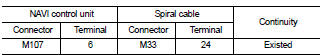
2. Check continuity between NAVI control unit harness connector and spiral cable harness connector.
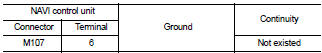
3. Check continuity between NAVI control unit harness connector and ground.
Is the inspection result normal? YES >> GO TO 2.
NO >> Repair harness or connector.
2.CHECK SPIRAL CABLE
Check spiral cable.
Is the inspection result normal? YES >> GO TO 3.
NO >> Replace spiral cable. Refer to SR-16, "Exploded View".
3.CHECK NAVI CONTROL UNIT VOLTAGE
1. Connect NAVI control unit connector and spiral cable connector.
2. Turn ignition switch ON.
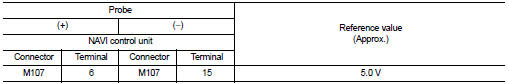
3. Check voltage between NAVI control unit harness connector.
Is the inspection result normal? YES >> GO TO 4.
NO >> Replace NAVI control unit. Refer to AV-84, "Removal and Installation".
4.CHECK STEERING SWITCH
1. Turn ignition switch OFF.
2. Check steering switch. Refer to AV-72, "Component Inspection".
Is the inspection result normal? YES >> INSPECTION END
NO >> Replace steering switch. Refer to AV-91, "Exploded View".
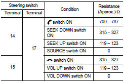
Component Inspection
Measure the resistance between the steering switch connector
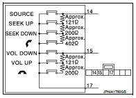
Standard
 Camera image signal circuit
Description
• The NAVI control unit supplies power to the rear view camera when receiving
a reverse signal.
• The rear view camera transmits camera images to the NAVI control unit when
power ...
 Steering switch signal B circuit
Description
Transmits the steering switch signal to NAVI control unit.
Diagnosis Procedure
1.CHECK STEERING SWITCH SIGNAL B CIRCUIT
1. Disconnect NAVI control unit connector and spiral cable conne ...
Other materials:
Additional service when replacing transaxle assembly
Description
Perform the following work after the transaxle assembly is replaced.
Erasing the calibration data
• The TCM acquires calibration data (individual characteristic value) of each
solenoid that is stored in the
ROM assembly (in the control valve). This enables the TCM to perform ac ...
Handling precaution
Nissan Dynamic Control System
• The engine torque, engine power, boost, and instantaneous fuel consumption
are provided for information
purposes only. They are not intended to prompt the driver to adjust driving
style. The readings may be
slightly delayed relative to the actual vehicle beha ...
Eco information
CAUTION
Do not adjust the display controls while driving so that full attention may
given to vehicle operation.
The following ECO INFO mode will appear on the display by pushing the ECO information
button, then turning the selection dial to scroll through the different screens.
While driving, ...
