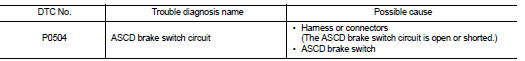
Nissan Juke Service and Repair Manual : P0504 ASCD brake SWI
DTC Logic
DTC DETECTION LOGIC
Diagnosis Procedure
1.CHECK GROUND CONNECTIONS
1. Turn ignition switch OFF and wait at least 20 seconds.
2. Check ground connection E38. Refer to Ground inspection in GI-44, "Circuit Inspection".
Is the inspection result normal? YES >> GO TO 2.
NO >> Repair or replace ground connection.
2.CHECK ASCD BRAKE SWITCH POWER SUPPLY CIRCUIT
1. Disconnect ACSD brake switch harness connector.
2. Check the voltage between ACSD brake switch harness connector and ground.
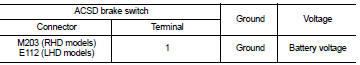
Is the inspection result normal? YES >> GO TO 3.
NO >> Repair open circuit or short to ground or short to power in harness or connectors.
3.CHECK ASCD BRAKE SWITCH INPUT SIGNAL CIRCUIT FOR OPEN AND SHORT
1. Check the continuity between ACSD brake switch harness connector and ECM harness connector.
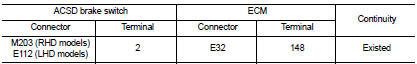
2. Also check harness for short to ground and short to power.
Is the inspection result normal? YES >> GO TO 4.
NO >> Repair open circuit or short to ground or short to power in harness or connectors.
4.CHECK ASCD BRAKE SWITCH
Refer to EC-957, "Component Inspection".
Is the inspection result normal? YES >> GO TO 5.
NO >> Replace ASCD brake switch.
5.CHECK INTERMITTENT INCIDENT
Refer to GI-42, "Intermittent Incident".
Is the inspection result normal? YES >> Replace ACSD brake switch.
NO >> Repair or replace.
Component Inspection
1.CHECK ASCD BRAKE SWITCH-I
1. Turn ignition switch OFF.
2. Disconnect ASCD brake switch harness connector.
3. Check the continuity between ASCD brake switch terminals under the following condition.
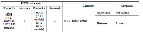
Is the inspection result normal? YES >> INSPECTION END
NO >> Replace ASCD brake switch.
 P0488 EGR system
DTC Logic
DTC DETECTION LOGIC
Diagnosis Procedure
1.CHECK EGR VOLUME CONTROL VALVE CONTROL CIRCUIT
1. Turn ignition switch OFF.
2. Disconnect EGR volume control valve harness connector and ECM ...
 P0525 ASCD system
DTC Logic
DTC DETECTION LOGIC
Diagnosis Procedure
1.CHECK GROUND CONNECTIONS
1. Turn ignition switch OFF and wait at least 20 seconds.
2. Check ground connection E38. Refer to Ground inspection ...
Other materials:
Brake pedal vibration or operation sound occurs
Description
• Brake pedal vibrates and motor sound from ABS actuator and electric unit
(control unit) occurs, when the
engine starts.
• Brake pedal vibrates during braking.
CAUTION:
Vibration may be felt during brake pedal is lightly depressed (just placing a
foot on it) in the follow ...
P17B8 high clutch solenoid
DTC Logic
DTC DETECTION LOGIC
DTC CONFIRMATION PROCEDURE
1.PREPARATION BEFORE WORK
If another "DTC CONFIRMATION PROCEDURE" occurs just before, turn ignition
switch OFF and wait for at
least 10 seconds, then perform the next test.
>> GO TO 2.
2.CHECK DTC DETECTION
1. S ...
Unbalance steering wheel turning force and return between
right and left
Description
Unbalance steering wheel turning force and return between right and left.
Diagnosis Procedure
1.CHECK THE ILLUMINATION OF THE EPS WARNING LAMP
Check the EPS warning lamp while engine is running.
Does the EPS warning lamp turn OFF?
YES >> GO TO 2.
NO >> Refer to STC ...
