Nissan Juke Service and Repair Manual : P0488 EGR system
DTC Logic
DTC DETECTION LOGIC
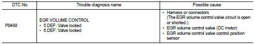
Diagnosis Procedure
1.CHECK EGR VOLUME CONTROL VALVE CONTROL CIRCUIT
1. Turn ignition switch OFF.
2. Disconnect EGR volume control valve harness connector and ECM harness connector.
3. Check the continuity between EGR volume control valve terminal harness connector and ECM harness connector.
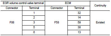
4. Also check harness for short to ground and short to power.
OK or NG OK >> GO TO 2.
NG >> Repair open circuit or short to ground or short to power in harness or connectors.
2.CHECK EGR VOLUME CONTROL VALVE
Refer to EC-954, "Component Inspection".
OK or NG OK >> GO TO 3.
NG >> Replace EGR volume control valve. Refer to EC-881, "Work Procedure".
3.CHECK EGR VOLUME CONTROL VALVE CONTROL POSITION SENSOR
Refer to EC-954, "Component Inspection".
OK or NG OK >> GO TO 4.
NG >> Replace EGR volume control valve. Refer to EC-881, "Work Procedure".
4.CHECK INTERMITTENT INCIDENT
Refer to GI-42, "Intermittent Incident".
>> INSPECTION END
Component Inspection
EGR VOLUME CONTROL VALVE
1. Disconnect EGR volume control valve harness connector.
2. Check resistance EGR volume control valve harness connector.
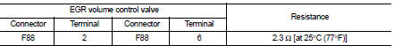
If NG, replace EGR volume control valve. Refer to EC-881, "Work Procedure".
EGR VOLUME CONTROL VALVE CONTROL POSITION SENSOR
1. Disconnect EGR volume control valve harness connector.
2. Check continuity EGR volume control valve harness connector.
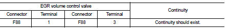
If NG, replace EGR volume control valve. Refer to EC-881, "Work Procedure".
 P0487 EGR volume control valve
DTC Logic
DTC DETECTION LOGIC
Diagnosis Procedure
1.CHECK EGR VOLUME CONTROL VALVE CONTROL CIRCUIT
1. Turn ignition switch OFF.
2. Disconnect EGR volume control valve harness connector and ECM ...
 P0504 ASCD brake SWI
DTC Logic
DTC DETECTION LOGIC
Diagnosis Procedure
1.CHECK GROUND CONNECTIONS
1. Turn ignition switch OFF and wait at least 20 seconds.
2. Check ground connection E38. Refer to Ground inspection ...
Other materials:
Door switch
Component Function Check
1.CHECK FUNCTION
1. Select “DOOR LOCK” of “BCM” using CONSULT-III.
2. Select “DOOR SW-DR”, “DOOR SW-AS”, “DOOR SW-RL”, “DOOR SW-RR”, “BACK DOOR SW”
in
“DATA MONITOR” mode.
3. Check that the function operates normally according to the fo ...
Precaution
Precaution for Supplemental Restraint System (SRS) "AIR BAG" and "SEAT
BELT
PRE-TENSIONER"
The Supplemental Restraint System such as “AIR BAG” and “SEAT BELT PRE-TENSIONER”,
used along
with a front seat belt, helps to reduce the risk or severity of injury to the
...
Refilling
1. IInstall reservoir tank if removed, and install radiator drain plug.
CAUTION:
Be sure to clean drain plug and install with new O-ring.
Radiator drain plug : Refer to CO-17, "Exploded View".
• If water drain plugs on cylinder block are removed, close and tighten them.
Refer to ...
