Nissan Juke Service and Repair Manual : P0487 EGR volume control valve
DTC Logic
DTC DETECTION LOGIC
Diagnosis Procedure
1.CHECK EGR VOLUME CONTROL VALVE CONTROL CIRCUIT
1. Turn ignition switch OFF.
2. Disconnect EGR volume control valve harness connector and ECM harness connector.
3. Check the continuity between EGR volume control valve terminal harness connector and ECM harness connector.
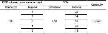
4. Also check harness for short to ground and short to power.
OK or NG OK >> GO TO 2.
NG >> Repair open circuit or short to ground or short to power in harness or connectors.
2.CHECK EGR VOLUME CONTROL VALVE
Refer to EC-952, "Component Inspection".
OK or NG OK >> GO TO 3.
NG >> Replace EGR volume control valve. Refer to EC-881, "Work Procedure".
3.CHECK EGR VOLUME CONTROL VALVE CONTROL POSITION SENSOR
Refer to EC-952, "Component Inspection".
OK or NG OK >> GO TO 4.
NG >> Replace EGR volume control valve. Refer to EC-881, "Work Procedure".
4.CHECK INTERMITTENT INCIDENT
Refer to GI-42, "Intermittent Incident".
>> INSPECTION END
Component Inspection
EGR VOLUME CONTROL VALVE
1. Disconnect EGR volume control valve harness connector.
2. Check resistance EGR volume control valve harness connector.
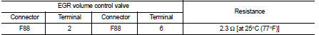
If NG, replace EGR volume control valve. Refer to EC-881, "Work Procedure".
EGR VOLUME CONTROL VALVE CONTROL POSITION SENSOR
1. Disconnect EGR volume control valve harness connector.
2. Check continuity EGR volume control valve harness connector.
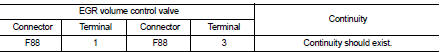
If NG, replace EGR volume control valve. Refer to EC-881, "Work Procedure".
 P047B exhaust gas pressure sensor 2
DTC Logic
DTC DETECTION LOGIC
Diagnosis Proce
1.CHECK GROUND CONNECTIONS
1. Turn ignition switch OFF and wait at least 20 seconds.
2. Check ground connection E38. Refer to Ground inspection in ...
 P0488 EGR system
DTC Logic
DTC DETECTION LOGIC
Diagnosis Procedure
1.CHECK EGR VOLUME CONTROL VALVE CONTROL CIRCUIT
1. Turn ignition switch OFF.
2. Disconnect EGR volume control valve harness connector and ECM ...
Other materials:
Range
The total driving distance your Nissan Leaf can cover on a single charge is dynamic. This range varies considerably based on a complex interplay of factors, including your current battery state of charge, prevailing weather conditions, ambient temperatures, specific usage patterns, the overall age o ...
Engine compartment
CAUTION
Never use a fuse of a higher or lower amperage rating than that specified
on the fuse box cover. This could damage the electrical system or cause a fire.
If any electrical equipment does not operate, check for an open fuse.
1. Be sure the ignition switch and the headlight switch are t ...
ECU diagnosis information
EPS control unit
Reference Value
VALUES ON THE DIAGNOSIS TOOL
CAUTION:
The output signal indicates the EPS control unit calculation data. The normal
values will be displayed
even in the event that the output circuit (harness) is open.
*1: Almost in accordance with the value of “MOTOR SIG ...
