Nissan Juke Service and Repair Manual : P047B exhaust gas pressure sensor 2
DTC Logic
DTC DETECTION LOGIC
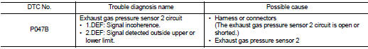
Diagnosis Proce
1.CHECK GROUND CONNECTIONS
1. Turn ignition switch OFF and wait at least 20 seconds.
2. Check ground connection E38. Refer to Ground inspection in GI-44, "Circuit Inspection".
Is the inspection result normal? YES >> GO TO 2.
NO >> Repair or replace ground connection.
2.CHECK EXHAUST GAS PRESSURE SENSOR 2 POWER SUPPLY CIRCUIT
1. Disconnect exhaust gas pressure sensor 2 harness connector.
2. Turn ignition switch ON.
3. Check the voltage between exhaust pressure sensor 2 harness connector and ground.
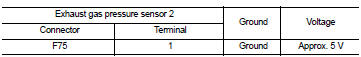
Is the inspection result normal? YES >> GO TO 3.
NO >> Repair open circuit or short to ground or short to power in harness or connectors.
3.CHECK EXHAUST GAS PRESSURE SENSOR 2 GROUND CIRCUIT FOR OPEN AND SHORT
1. Turn ignition switch OFF and wait at least 20 seconds.
2. Check the continuity between exhaust gas pressure sensor 2 harness connector and ECM harness connector.
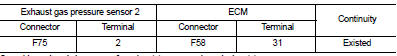
3. Also check harness for short to ground and short to power.
Is the inspection result normal? YES >> GO TO 4.
NO >> Repair open circuit or short to ground or short to power in harness or connectors.
4.CHECK EXHAUST GAS PRESSURE SENSOR 2 INPUT SIGNAL CIRCUIT FOR OPEN AND SHORT
1. Check the continuity between exhaust gas pressure sensor 2 harness connector and ECM harness connector.
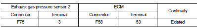
2. Also check harness for short to ground and short to power.
Is the inspection result normal? YES >> GO TO 5.
NO >> Repair open circuit or short to ground or short to power in harness or connectors.
5.CHECK INTERMITTENT INCIDENT
Refer to GI-42, "Intermittent Incident".
Is the inspection result normal? YES >> Replace exhaust gas pressure sensor 2.
NO >> Repair or replace.
 P047A exhaust gas pressure sensor 2
DTC Logic
DTC DETECTION LOGIC
NOTE:
If DTC P047A is displayed with DTC P0651, first perform trouble diagnosis for
DTC P0651. Refer to EC-975,
"DTC Logic".
Diagnosis Procedure
1.CHE ...
 P0487 EGR volume control valve
DTC Logic
DTC DETECTION LOGIC
Diagnosis Procedure
1.CHECK EGR VOLUME CONTROL VALVE CONTROL CIRCUIT
1. Turn ignition switch OFF.
2. Disconnect EGR volume control valve harness connector and ECM ...
Other materials:
Charging system preliminary inspection
Inspection Procedure
1.CHECK BATTERY TERMINALS CONNECTION
Check if battery terminals are clean and tight.
Is the inspection result normal?
YES >> GO TO 2.
NO >> Repair battery terminals connection.
2.CHECK FUSE
Check for blown fuse and fusible link.
Is the inspection resu ...
Push starting
Do not attempt to start the engine by pushing.
CAUTION
• Continuously Variable Transmission (CVT) models cannot be pushstarted or
tow-started. Attempting to do so may cause transmission damage.
• Three-way catalyst equipped models should not be started by pushing since the
three way catal ...
P0222, P0223 TP sensor
DTC Logic
DTC DETECTION LOGIC
NOTE:
If DTC P0222 or P0223 is displayed with DTC P0643, first perform the trouble
diagnosis for DTC P0643.
Refer to EC-686, "DTC Logic".
DTC CONFIRMATION PROCEDURE
1.PRECONDITIONING
If DTC Confirmation Procedure has been previously conducted, alw ...
