Nissan Juke Service and Repair Manual : B2581, B2582 intake sensor
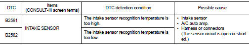
DTC Logic
DTC DETECTION LOGIC
NOTE
:
• If DTC is displayed along with DTC U1000, first perform the trouble diagnosis
for DTC U1000. Refer to HAC-
141, "DTC Logic".
• If DTC is displayed along with DTC U1010, first perform the trouble diagnosis for DTC U1010. HAC-142, "DTC Logic".
DTC CONFIRMATION PROCEDURE
1.PERFORM DTC CONFIRMATION PROCEDURE
 With CONSULT-III
1. Turn ignition switch ON.
2. Select “Self Diagnostic Result” mode of “HVAC” using CONSULT-III.
3. Check DTC.
Is DTC detected? YES >> Refer to HAC-149, "Diagnosis Procedure".
NO >> INSPECTION END
Diagnosis Proced
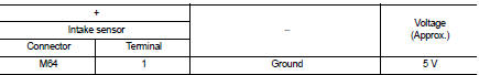
1.CHECK INTAKE SENSOR POWER SUPPLY
1. Turn ignition switch OFF.
2. Disconnect intake sensor connector.
3. Turn ignition switch ON.
4. Check voltage between intake sensor harness connector and ground.
Is the inspection result normal? YES >> GO TO 2.
NO >> GO TO 4.
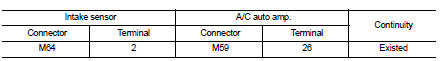
2.CHECK INTAKE SENSOR GROUND CIRCUIT FOR OPEN
1. Turn ignition switch OFF.
2. Disconnect A/C auto amp. connector.
3. Check continuity between intake sensor harness connector and A/C auto amp harness connector
Is the inspection result normal?
YES >> GO TO 3.
NO >> Repair harness or connector.
3.CHECK INTAKE SENSOR
Check intake sensor. Refer to HAC-147, "Component Inspection".
Is the inspection result normal? YES >> Replace A/C auto amp. Refer to HAC-188, "Removal and Installation".
NO >> Replace intake sensor. Refer to HAC-192, "Removal and Installation".
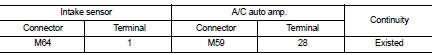
4.CHECK INTAKE SENSOR POWER SUPPLY CIRCUIT FOR OPEN
1. Turn ignition switch OFF.
2. Disconnect A/C auto amp. connector.
3. Check continuity between intake sensor harness connector and A/C auto amp. harness connector.
Is the inspection result normal? YES >> GO TO 5.
NO >> Repair harness or connector.
5.CHECK INTAKE SENSOR POWER SUPPLY CIRCUIT FOR SHORT
Check continuity between intake sensor harness connector and ground.
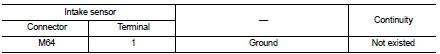
Is the inspection result normal? YES >> Replace A/C auto amp. Refer to HAC-188, "Removal and Installation".
NO >> Repair harness or connector.
Component Inspection
1.CHECK INTAKE SENSOR
1. Remove intake sensor. Refer to HAC-192, "Removal and Installation".
2. Check resistance between intake sensor terminals. Refer to applicable table for the normal value.
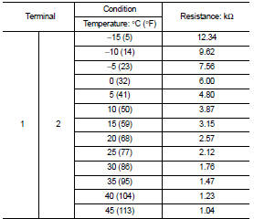
Is the inspection result normal? YES >> INSPECTION END
NO >> Replace intake sensor. Refer to HAC-192, "Removal and Installation".
 B257B, B257C ambient sensor
DTC Logic
DTC DETECTION LOGIC
NOTE:
• If DTC is displayed along with DTC U1000, first perform the trouble diagnosis
for DTC U1000. Refer to HAC-
141, "DTC Logic".
• If DTC is disp ...
 B2630, B2631 sunload sensor
DTC Logic
DTC DETECTION LOGIC
NOTE:
• If DTC is displayed along with DTC U1000, first perform the trouble diagnosis
for DTC U1000. Refer to HAC-
141, "DTC Logic".
• If DTC is di ...
Other materials:
Front seat (4WD)
Exploded View
DRIVER SEAT
LHD models
1. Headrest
2. Headrest holder (locked)
3. Headrest holder (free)
4. Seatback assembly
(with heater seat only)
5. Inner lower cover
6. Seatback trim
(without heater seat only)
7. Seatback pad
(without heater seat only)
8. Seat belt buckle
9. A ...
P1650 starter motor relay 2
Description
ECM controls ON/OFF state of the starter relay, according to the engine and
vehicle condition. Models with no
Intelligent Key System transmit a control signal directly to IPDM E/R. On the
other hand, models with the Intelligent
Key System transmit a control signal to IPDM E/R by w ...
Component parts
Component Parts Location
1. Back door lock assembly
2. Front door lock assembly (driver
side)
3. Front door switch (driver side)
4. Power window main switch
(door lock/unlock switch)
5. Key switch
6. Combination meter
7. Door lock status indicator
8. Remote keyless entry receiver
9. ...
