Nissan Juke Service and Repair Manual : B2630, B2631 sunload sensor
DTC Logic
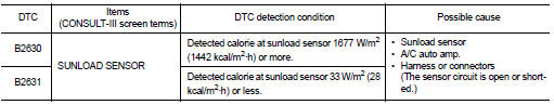
DTC DETECTION LOGIC
NOTE
:
ŌĆó If DTC is displayed along with DTC U1000, first perform the trouble diagnosis
for DTC U1000. Refer to HAC-
141, "DTC Logic".
ŌĆó If DTC is displayed along with DTC U1010, first perform the trouble diagnosis for DTC U1010. HAC-142, "DTC Logic".
ŌĆó Sunload sensor may register a malfunction when indoors, at dusk, or at other times when light is insufficient.
When performing the diagnosis indoors, use a lamp (60 W or more) that is pointed at the sunload sensor.
DTC CONFIRMATION PROCEDURE
1.PERFORM DTC CONFIRMATION PROCEDURE
 With CONSULT-III
1. Turn ignition switch ON.
2. Select ŌĆ£Self Diagnostic ResultŌĆØ mode of ŌĆ£HVACŌĆØ using CONSULT-III.
3. Check DTC.
Is DTC detected? YES >> Refer to HAC-152, "Diagnosis Procedure".
NO >> INSPECTION END
Diagnosis Procedure
1.CHECK SUNLOAD SENSOR POWER SUPPLY
1. Turn ignition switch OFF.
2. Disconnect sunload sensor connector.
3. Turn ignition switch ON.
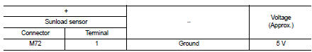
4. Check voltage between sunload sensor harness connector and ground.
Is the inspection result normal? YES >> GO TO 2.
NO >> GO TO 4.
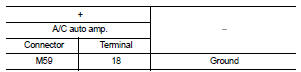
2.CHECK SUNLOAD SENSOR GROUND CIRCUIT FOR OPEN
1. Turn ignition switch OFF.
2. Disconnect A/C auto amp. connector.
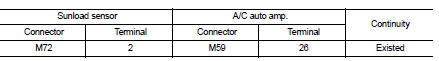
3. Check continuity between sunload sensor harness connector and A/C auto amp harness connector.
Is the inspection result normal? YES >> GO TO 3.
NO >> Repair harness or connector.
3.CHECK SUNLOAD SENSOR
1. Disconnect A/C auto amp. connector.
2. Check sunload sensor. Refer to HAC-147, "Component Inspection".
Is the inspection result normal? YES >> Replace A/C auto amp. Refer to HAC-188, "Removal and Installation".
NO >> Replace sunload sensor. Refer to HAC-191, "Removal and Installation".
4.CHECK SUNLOAD SENSOR POWER SUPPLY CIRCUIT FOR OPEN
1. Turn ignition switch OFF.
2. Disconnect A/C auto amp. connector.
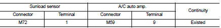
3. Check continuity between sunload sensor harness connector and A/C auto amp. harness connector.
Is the inspection result normal? YES >> GO TO 5.
NO >> Repair harness or connector.
5.CHECK SUNLOAD SENSOR POWER SUPPLY CIRCUIT FOR SHORT
Check continuity between sunload sensor harness connector and ground.
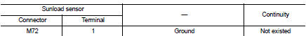
Is the inspection result normal? YES >> Replace A/C auto amp. Refer to HAC-188, "Removal and Installation".
NO >> Repair harness or connector.
Component Inspection
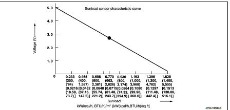
1.CHECK SUNLOAD SENSOR
1. Turn ignition switch ON.
2. Check voltage between A/C auto amp. harness connector and ground. Refer to applicable table for the normal value.
NOTE
:
ŌĆó When checking indoors, use a lamp of approximately 60 W. Move the lamp towards
and away from the
sensor to check.
ŌĆó The sunload amount produced by direct sunshine in fair weather is equivalent to approximately 0.77 kW/m2 (662 kcal/m2┬Ęh).
Is the inspection result normal? YES >> INSPECTION END
NO >> Replace sunload sensor. Refer to HAC-191, "Removal and Installation".
 B2581, B2582 intake sensor
DTC Logic
DTC DETECTION LOGIC
NOTE:
ŌĆó If DTC is displayed along with DTC U1000, first perform the trouble diagnosis
for DTC U1000. Refer to HAC-
141, "DTC Logic".
ŌĆó If DTC is disp ...
 B2632, B2633 air mix door motor PBR
DTC Logic
DTC DETECTION LOGIC
DTC CONFIRMATION PROCEDURE
1.PERFORM DTC CONFIRMATION PROCEDURE
With CONSULT-III
1. Turn ignition switch ON.
2. Select ŌĆ£Self Diagnostic ResultŌĆØ mode of ŌĆ£HVA ...
Other materials:
Event Data Recorders (EDR)
This vehicle is equipped with an Event Data Recorder (EDR). The main purpose
of an EDR is to record, in certain crash or near crash-like situations, such as
an air bag deployment or hitting a road obstacle, data that will assist in understanding
how a vehicleŌĆÖs systems performed.
The EDR is ...
Corrosion protection
Most common factors contributing to vehicle corrosion
The persistent accumulation of moisture-retaining dirt, road grime, and organic debris within hidden body panel sections, structural cavities, and hard-to-reach areas of your Nissan Leaf.
Compromised integrity of the facto ...
C1606 EPS motor
DTC Logic
DTC DETECTION LOGIC
DTC CONFIRMATION PROCEDURE
1.PRECONDITIONING
If ŌĆ£DTC CONFIRMATION PROCEDUREŌĆØ has been previously conducted, always turn
ignition switch OFF and
wait at least 10 seconds before conducting the next test.
>> GO TO 2.
2.DTC REPRODUCTION PROCEDURE
W ...
