Nissan Juke Service and Repair Manual : C1606 EPS motor
DTC Logic
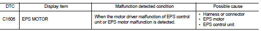
DTC DETECTION LOGIC
DTC CONFIRMATION PROCEDURE
1.PRECONDITIONING
If “DTC CONFIRMATION PROCEDURE” has been previously conducted, always turn ignition switch OFF and wait at least 10 seconds before conducting the next test.
>> GO TO 2.
2.DTC REPRODUCTION PROCEDURE
 With CONSULT-III
1. Turn the ignition switch OFF to ON.
2. Perform “EPS” self-diagnosis.
Is DTC “C1606” detected? YES >> Proceed to diagnosis procedure. Refer to STC-22, "Diagnosis Procedure".
NO >> INSPECTION END
Diagnosis Procedure
1.PERFORM SELF-DIAGNOSIS
With CONSULT-III
1. Erase self-diagnostic results for “EPS”.
2. Turn the ignition switch OFF, and then wait 10 seconds and more.
3. Perform self-diagnosis for “EPS”.
Is DTC “C1606” detected? YES >> EPS motor is malfunctioning. Replace steering column assembly. Refer to ST-10, "Removal and Installation".
NO >> Check EPS control unit pin terminals for damage or loose connection with harness connector. If any items are damaged, repair or replace error-detected parts.
 C1604 torque sensor
DTC Logic
DTC DETECTION LOGI
DTC CONFIRMATION PROCEDURE
1.PRECONDITIONING
If “DTC CONFIRMATION PROCEDURE” has been previously conducted, always turn
ignition switch OFF and
wait at least ...
 C1607, C1608 EPS control unit
DTC Logic
DTC DETECTION LOGIC
DTC CONFIRMATION PROCEDURE
1.PRECONDITIONING
If “DTC CONFIRMATION PROCEDURE” has been previously conducted, always turn
ignition switch OFF and
wait at least ...
Other materials:
P047B exhaust gas pressure sensor 2
DTC Logic
DTC DETECTION LOGIC
Diagnosis Proce
1.CHECK GROUND CONNECTIONS
1. Turn ignition switch OFF and wait at least 20 seconds.
2. Check ground connection E38. Refer to Ground inspection in GI-44, "Circuit
Inspection".
Is the inspection result normal?
YES >> GO TO 2.
...
STRG branch line circuit
Diagnosis Procedure
1.CHECK CONNECTOR
1. Turn the ignition switch OFF.
2. Disconnect the battery cable from the negative terminal.
3. Check the terminals and connectors of the steering angle sensor for damage,
bend and loose connection
(unit side and connector side).
Is the inspection resu ...
P0520 EOP sensor
DTC Logic
DTC DETECTION LOGIC
DTC CONFIRMATION PROCEDURE
1.PRECONDITIONING
If DTC Confirmation Procedure has been previously conducted, always perform
the following procedure
before conducting the next test.
1. Turn ignition switch OFF and wait at least 10 seconds.
2. Turn ignition swit ...
