Nissan Juke Service and Repair Manual : Drive belt
Checking Drive Belts
WARNING:
Be sure to perform when the engine is stopped.
1. Inspect belts for cracks, fraying, wear and oil. If necessary, replace.
2. Evaluate manually if the belt is enough tensioned (tension cannot be measured by way of frequency meter).
CAUTION:
Auto-tensioner must be replaced with a new one when the
belt is replaced.
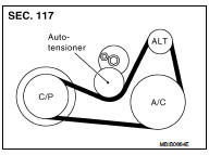
Tension Adjustment
Belt tensioning is not necessary, as it is automatically adjusted by auto-tensioner.
Removal and Installation
CAUTION: • Replace any belt that has been removed with a new one.
• Auto-tensioner must be replaced with new ones when the belt is replaced.
• Never run the engine without the drive belts to avoid damaging the crankshaft pulley
.
REMOVAL
1. Remove engine undercover.
2. Remove RH front wheel.
3. Remove fender protector RH. Refer to EXT-22, "Exploded View".
4. Remove drive belt.
• Turn clockwise adjusting bolt.
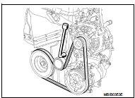
5. If necessary, remove auto-tensioner.
INSTALLATION
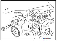
1. Install auto-tensioner mounting bolt.
Auto-tensioner mounting bolt : 40 N·m (4.1 kg-m, 30 ft-lb)
• Align the notch and tighten mounting bolt.
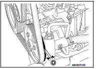
2. Install the drive belt.
CAUTION:
• Make sure belt is correctly engaged with the pulley
groove.
• Check for oil and coolant on belt and each pulley groove.
• Certain drive belts have five teeth whereas the air conditioning compressor pulley, power-assisted steering pump pulley, and alternator pulley all have six teeth.In this case, it is essential to check that inner tooth (O) of the pulleys remains free when fitting the drive belt.
Never turn the engine in the opposite direction to its normal operating direction.
Use a brush to remove any deposits from the crankshaft pulley V grooves.
For engines fitted with a mechanical tensioning roller, it is essential to replace the tensioning roller mounting bolts.
3. Make sure that tension of each belt is within the standard.

 Air cleaner filter
Exploded View
1. Turbocharger air inlet pipe
2. Clamp
3. Air duct (suction)
4. Air mass flow sensor
5. O-ring
6. Air duct (inlet)
7. Grommet
8. Air cleaner case
9. Air cleaner filter
...
Other materials:
Diagnosis system [ABS actuator and electric unit (control
unit)]
CONSULT-III Function
APPLICATION ITEMS
CONSULT-III can display each diagnostic item using the diagnostic test modes
as follows.
*1: The following diagnosis information is erased by erasing.
• DTC
• Freeze frame data (FFD)
*2: Although “Function Test” is selectable, do not use its.
...
Timing chain
Exploded View
1. Timing chain slack guide
2. Timing chain tensioner
3. Camshaft sprocket (EXH)
4. Camshaft sprocket (INT)
5. Plug 6. Front oil seal
7. Crankshaft pulley
8. Crankshaft pulley bolt
9. Front cover
10. Crankshaft sprocket
11. Crankshaft sprocket key
12. Oil pump sproc ...
Precautions when starting and driving
WARNING
• Do not leave children or adults who would normally require the support
of others alone in your vehicle. Pets should not be left alone either. They could
accidentally injure themselves or others through inadvertent operation of the vehicle.
Also, on hot, sunny days, temperatu ...
