Nissan Juke Service and Repair Manual : Air cleaner filter
Exploded View
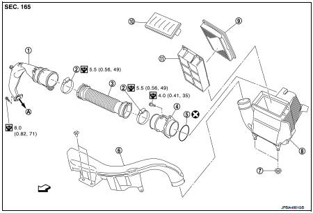
1. Turbocharger air inlet pipe
2. Clamp
3. Air duct (suction)
4. Air mass flow sensor
5. O-ring
6. Air duct (inlet)
7. Grommet
8. Air cleaner case
9. Air cleaner filter
10. Cover
11. Holder
A. : To turbocharger
 : Vehicle front
 : N·m (kg-m, in-lb)
 : Always replace after every
disassembly.
Removal and Installation
REMOVAL
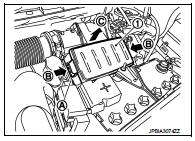
1. Push the tabs (A) of both ends of the air cleaner cover (1) into the inside (B).
2. Pull up the air cleaner cover forward (C) and remove it.
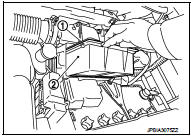
3. Remove the air cleaner filter (1) and holder (2) assembly from the air cleaner case.
4. Remove the air cleaner filter from the holder.
INSTALLATION
Install in the reverse order of removal.
 Drive belt
Checking Drive Belts
WARNING:
Be sure to perform when the engine is stopped.
1. Inspect belts for cracks, fraying, wear and oil. If necessary,
replace.
2. Evaluate manually if the belt is enough ...

Other materials:
Normal operating condition
Description
RELATED TO AUDIO
• The majority of the audio malfunctions are the result of outside causes
(bad CD, electromagnetic interference,
etc.). Check the symptoms below to diagnose the malfunction.
• The vehicle itself can be a source of noise if noise prevention parts or
electrical ...
12-volt battery
Maintain the external surface of the 12-volt battery in a clean and dry condition. Should corrosion appear on the terminals or casing, clean the battery using a mild solution of baking soda mixed with water, ensuring that none of this solution enters the battery cells ...
Precaution for Supplemental Restraint System (SRS) "AIR BAG" and "SEAT BELT
PRE-TENSIONER"
The Supplemental Restraint System such as “AIR BAG” and “SEAT BELT PRE-TENSIONER”,
used along
with a front seat belt, helps to reduce the risk or severity of injury to the
driver and front passenger for certain
types of collision. Information necessary to service the system safely is
...
