Nissan Juke Service and Repair Manual : P2120 APP sensor
DTC Logic
DTC DETECTION LOGIC
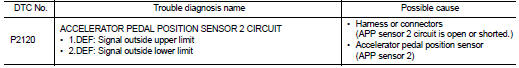
Diagnosis Procedure
1.CHECK GROUND CONNECTIONS
1. Turn ignition switch OFF.
2. Check ground connection E38. Refer to Ground inspection in GI-44, "Circuit Inspection".
Is the inspection result normal? YES >> GO TO 2.
NO >> Repair or replace ground connection.
2.CHECK ACCELERATOR PEDAL POSITION SENSOR POWER SUPPLY CIRCUIT
1. Disconnect accelerator pedal position sensor harness connector.
2. Turn ignition switch ON.
3. Check the voltage between accelerator pedal position sensor connector and ground.
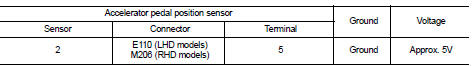
Is the inspection result normal? YES >> GO TO 4.
NO >> GO TO 3.
3.DETECT MALFUNCTIONING PART
• Harness connectors E105, M77 (RHD models) • Harness connectors M95, M202 (RHD models) • Harness for open or short between ECM and accelerator pedal position sensor
>> Repair open circuit or short to ground or short to power in harness or connector.
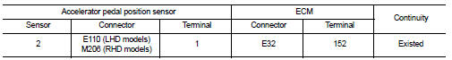
4.CHECK ACCELERATOR PEDAL POSITION SENSOR GROUND CIRCUIT FOR OPEN AND SHORT
1. Turn ignition switch OFF.
2. Disconnect accelerator pedal position sensor.
3. Check the continuity between accelerator pedal position sensor harness connector and ECM harness connector.
4. Also check harness for short to ground and short to power.
Is the inspection result normal? YES >> GO TO 6.
NO >> GO TO 5.
5.DETECT MALFUNCTIONING PART
• Harness connectors E105, M77 (RHD models) • Harness connectors M95, M202 (RHD models) • Harness for open or short between ECM and accelerator pedal position sensor
>> Repair open circuit or short to ground or short to power in harness or connector.
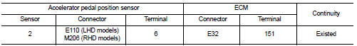
6.CHECK ACCELERATOR PEDAL POSITION SENSOR INPUT SIGNAL CIRCUIT FOR OPEN AND SHORT
1. Check the continuity between accelerator pedal position sensor harness connector and ECM harness
2. Also check harness for short to ground and short to power.
Is the inspection result normal? YES >> GO TO 8.
NO >> GO TO 7.
7.DETECT MALFUNCTIONING PART
• Harness connectors E105, M77 (RHD models) • Harness connectors M95, M202 (RHD models) • Harness for open or short between ECM and accelerator pedal position sensor
>> Repair open circuit or short to ground or short to power in harness or connector.
8.CHECK ACCELERATOR PEDAL POSITION SENSOR
Refer to EC-1001, "Component Inspection".
Is the inspection result normal? YES >> GO TO 9.
NO >> Replace accelerator pedal position sensor.
9.CHECK INTERMITTENT INCIDENT
Refer to GI-42, "Intermittent Incident", ???INCIDENT SIMULATION TESTS??? and ???GROUND INSPECTION???.
>> INSPECTION END
Component Inspection
1.CHECK ACCELERATOR PEDAL POSITION SENSOR
1. Turn ignition switch OFF.
2. Disconnect accelerator pedal position sensor harness connector.
3. Check resistance between accelerator pedal position sensor as follows.
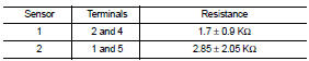
Is the inspection result normal? YES >> INSPECTION END
NO >> Replace accelerator pedal position sensor.
 P2119 electric throttle control function
DTC Logic
DTC DETECTION LOGIC
Diagnosis Procedure
1.CHECK INTERMITTENT INCIDENT
Refer to GI-42, "Intermittent Incident".
Is the inspection result normal?
YES >> GO TO 2.
N ...
 P2226 baro sensor
DTC Logic
DTC DETECTION LOGIC
Diagnosis Procedure
1.REPLACE ECM
Perform EC-879, "Work Procedure".
>> INSPECTION END ...
Other materials:
Precaution Necessary for Steering Wheel Rotation after Battery Disconnect
NOTE:
• Before removing and installing any control units, first turn the ignition
switch to the LOCK position, then disconnect
both battery cables.
• After finishing work, confirm that all control unit connectors are connected
properly, then re-connect both
battery cables.
• Always us ...
P0171 fuel injection system function
DTC Logic
DTC DETECTION LOGIC
With the Air/Fuel Mixture Ratio Self-Learning Control, the actual mixture
ratio can be brought closely to the
theoretical mixture ratio based on the mixture ratio feedback signal from the
A/F sensor 1. The ECM calculates
the necessary compensation to correct the ...
