Nissan Juke Service and Repair Manual : Remote keyless entry receiver
Component Function Check
1.CHECK FUNCTION
1. Select “DOOR LOCK” of “BCM” using CONSULT-III.
2. Select “KEYLESS ” or “KEYLESS UNLOCK” in “DATA MONITOR” mode.
3. Check that the function operates normally according to the following conditions.
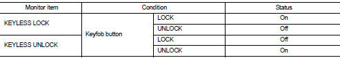
It the inspection result normal? YES >> Remote keyless entry receiver is OK.
NO >> Refer to DLK-404, "Diagnosis Procedure".
Diagnosis Procedure
1.CHECK REMOTE KEYLESS ENTRY RECEIVER GROUND CIRCUIT
1. Turn ignition switch OFF.
2. Disconnect BCM connector and remote keyless entry receiver connector.
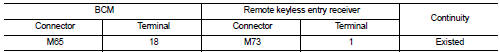
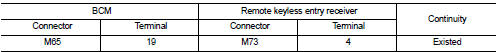
3. Check continuity between BCM harness connector and remote keyless entry receiver harness connector.
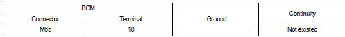
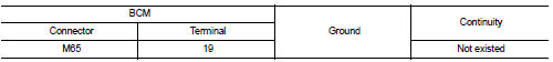
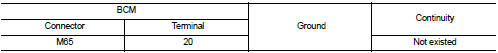
4. Check continuity between BCM harness connector and ground.
Is the inspection result normal? YES >> GO TO 2.
NO >> Repair or replace harness.
2.CHECK REMOTE KEYLESS ENTRY RECEIVER POWER SUPPLY
1. Reconnect BCM connector.
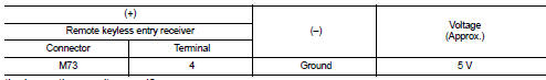
2. Check voltage between remote keyless entry receiver harness connector and ground.
Is the inspection result normal? YES >> GO TO 4.
NO >> GO TO 3.
3.CHECK REMOTE KEYLESS ENTRY RECEIVER CIRCUIT 1
1. Disconnect BCM connector 2. Check continuity between BCM harness connector and remote keyless entry receiver harness connector.
3. Check continuity between BCM harness connector and ground.
Is the inspection result normal? YES >> Replace BCM. Refer to BCS-161, "Removal and Installation".
NO >> Repair or replace harness.
4.CHECK REMOTE KEYLESS ENTRY RECEIVER OUTPUT SIGNAL
1. Reconnect remote keyless entry receiver connector.
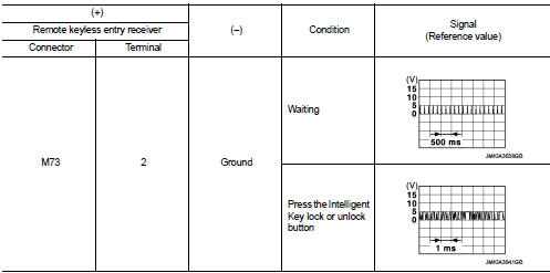
2. Check signal between remote keyless entry receiver harness connector and ground using oscilloscope.
Is the inspection result normal? YES >> GO TO 5.
NO >> Replace remote keyless entry receiver.
5.CHECK REMOTE KEYLESS ENTRY RECEIVER CIRCUIT 2
1. Disconnect BCM connector and remote keyless entry receiver connector.
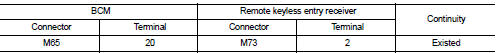
2. Check continuity between BCM harness connector and remote keyless entry receiver harness connector.
3. Check continuity between BCM harness connector and ground.
Is the inspection result normal? YES >> Replace BCM. Refer to BCS-161, "Removal and Installation".
NO >> Repair or replace harness.
 Keyfob battery
Component Function Check
1.CHECK FUNCTION
Check door lock and unlock operation with keyfob button.
Is the inspection result normal?
YES >> Keyfob is OK.
NO >> Refer to DLK-403, &q ...
 Super lock actuator
Driver side
DRIVER SIDE : Component Function Check
1.CHECK FUNCTION
1. Select “DOOR LOCK” of “BCM” using CONSULT-III.
2. Select “SUPER LOCK” in “ACTIVE TEST” mode.
3. Check that t ...
Other materials:
P0120 TP sensor
DTC Logic
DTC DETECTION LOGIC
Diagnosis Procedure
1.CHECK GROUND CONNECTIONS
1. Turn ignition switch OFF and wait at least 20 seconds.
2. Check ground connection E38. Refer to Ground inspection in GI-44, "Circuit
Inspection".
Is the inspection result normal?
YES >> GO TO ...
Door cable
Exploded View
LEFT SIDE
1. A/C unit assembly
2. Intake door lever
3. Intake door link
4. Intake door cable
5. Air mix door cable
6. Upper air mix door rod
7. Upper air mix door lever
8. Lower air mix door lever
9. Lower air mix door rod
10. Air mix door link
A. To A/C control
RI ...
Tire labeling
Federal law requires tire manufacturers to place standardized information on
the sidewall of all tires. This information identifies and describes the fundamental
characteristics of the tire and also provides the tire identification number (TIN)
for safety standard certification. The TIN can be ...
