Nissan Juke Service and Repair Manual : Super lock actuator
Driver side
DRIVER SIDE : Component Function Check
1.CHECK FUNCTION
1. Select “DOOR LOCK” of “BCM” using CONSULT-III.
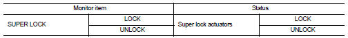
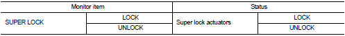
2. Select “SUPER LOCK” in “ACTIVE TEST” mode.
3. Check that the function operates normally according to the following conditions.
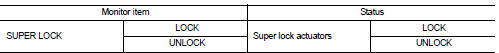
Is the inspection result normal? YES >> Super lock actuator is OK.
NO >> Refer to DLK-407, "DRIVER SIDE : Diagnosis Procedure".
DRIVER SIDE : Diagnosis Procedure
1.CHECK SUPER LOCK ACTUATOR INPUT SIGNAL
1. Turn ignition switch OFF.
2. Disconnect front door lock assembly (driver side) connector.
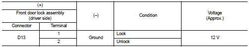
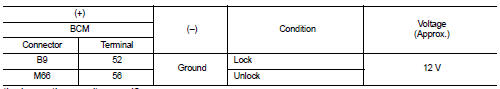
3. Check voltage between front door lock assembly (driver side) harness connector and ground.
Is the inspection result normal? YES >> Replace front door lock assembly (driver side).
NO >> GO TO 2.
2.CHECK SUPER LOCK ACTUATOR CIRCUIT
1. Disconnect BCM connector and all door lock assembly connector.
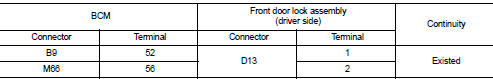
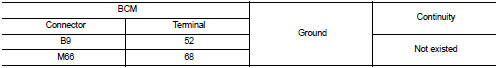
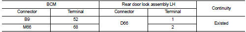
2. Check continuity between BCM harness connector and front door lock assembly (driver side) harness connector.
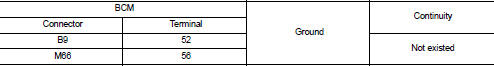
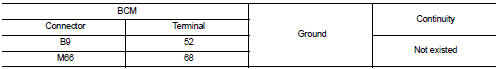
3. Check continuity between BCM harness connector and ground.
Is the inspection result normal? YES >> GO TO 3.
NO >> Repair or replace harness.
3.CHECK BCM OUTPUT SIGNAL
1. Connect BCM connector.
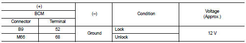
2. Check voltage between BCM harness connector and ground.
Is the inspection result normal? YES >> Check for internal short of each super lock actuator.
NO >> Replace BCM. Refer to BCS-161, "Removal and Installation".
Passenger side
PASSENGER SIDE : Component Function Check
1.CHECK FUNCTION
1. Select “DOOR LOCK” of “BCM” using CONSULT-III.
2. Select “SUPER LOCK” in “ACTIVE TEST” mode.
3. Check that the function operates normally according to the following conditions.
Is the inspection result normal? YES >> Super lock actuator is OK.
NO >> Refer to DLK-408, "PASSENGER SIDE : Diagnosis Procedure".
PASSENGER SIDE : Diagnosis Procedure
1.CHECK SUPER LOCK ACTUATOR INPUT SIGNAL
1. Turn ignition switch OFF.
2. Disconnect front door lock assembly (passenger side) connector.
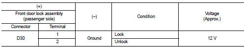
3. Check voltage between front door lock assembly (passenger side) harness connector and ground.
Is the inspection result normal? YES >> Replace front door lock assembly (passenger side).
NO >> GO TO 2.
2.CHECK SUPER LOCK ACTUATOR CIRCUIT
1. Disconnect BCM connector and all door lock assembly connector.
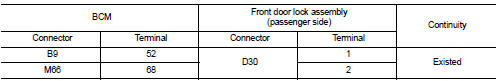
2. Check continuity between BCM harness connector and front door lock assembly (passenger side) harness connector
3. Check continuity between BCM harness connector and ground.
Is the inspection result normal? YES >> GO TO 3.
NO >> Repair or replace harness.
3.CHECK BCM OUTPUT SIGNAL
1. Connect BCM connector.
2. Check voltage between BCM harness connector and ground.
Is the inspection result normal? YES >> Check for internal short of each super lock actuator.
NO >> Replace BCM. Refer to BCS-161, "Removal and Installation".
Rear LH
REAR LH : Component Function Check
1.CHECK FUNCTION
1. Select “DOOR LOCK” of “BCM” using CONSULT-III.
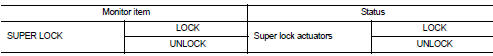
2. Select “SUPER LOCK” in “ACTIVE TEST” mode.
3. Check that the function operates normally according to the following conditions.
Is the inspection result normal? YES >> Super lock actuator is OK.
NO >> Refer to DLK-409, "REAR LH : Diagnosis Procedure".
REAR LH : Diagnosis Procedure
1.CHECK SUPER LOCK ACTUATOR INPUT SIGNAL
1. Turn ignition switch OFF.
2. Disconnect rear door lock assembly LH connector.
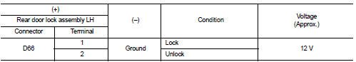
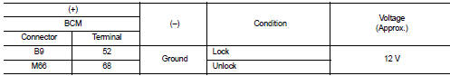
3. Check voltage between rear door lock assembly LH harness connector and ground.
Is the inspection result normal? YES >> Replace rear door lock assembly LH.
NO >> GO TO 2.
2.CHECK SUPER LOCK ACTUATOR CIRCUIT
1. Disconnect BCM connector and all door lock assembly connector.
2. Check continuity between BCM harness connector and rear door lock assembly LH harness connector.
3. Check continuity between BCM harness connector and ground.
Is the inspection result normal? YES >> GO TO 3.
NO >> Repair or replace harness.
3.CHECK BCM OUTPUT SIGNAL
1. Connect BCM connector.
2. Check voltage between BCM harness connector and ground.
Is the inspection result normal? YES >> Check for internal short of each super lock actuator.
NO >> Replace BCM. Refer to BCS-161, "Removal and Installation".
Rear RH
REAR RH : Component Function Check
1.CHECK FUNCTION
1. Select “DOOR LOCK” of “BCM” using CONSULT-III.
2. Select “SUPER LOCK” in “ACTIVE TEST” mode.
3. Check that the function operates normally according to the following conditions.
Is the inspection result normal? YES >> Back door lock actuator is OK.
NO >> Refer to DLK-411, "REAR RH : Diagnosis Procedure".
REAR RH : Diagnosis Procedure
1.CHECK SUPER LOCK ACTUATOR INPUT SIGNAL
1. Turn ignition switch OFF.
2. Disconnect rear door lock assembly RH connector.
3. Check voltage between rear door lock assembly RH harness connector and ground.
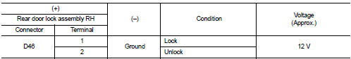
Is the inspection result normal? YES >> Replace rear door lock assembly RH.
NO >> GO TO 2.
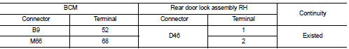
2.CHECK SUPER LOCK ACTUATOR CIRCUIT
1. Disconnect BCM connector and all door lock assembly connector.
2. Check continuity between BCM harness connector and rear door lock assembly RH harness connector.
3. Check continuity between BCM harness connector and ground.
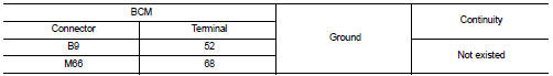
Is the inspection result normal? YES >> GO TO 3.
NO >> Repair or replace harness.
3.CHECK BCM OUTPUT SIGNAL
1. Connect BCM connector.
2. Check voltage between BCM harness connector and ground.
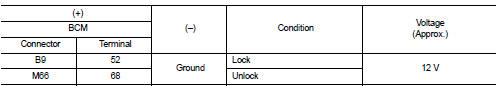
Is the inspection result normal? YES >> Check for internal short of each super lock actuator.
NO >> Replace BCM. Refer to BCS-161, "Removal and Installation".
 Remote keyless entry receiver
Component Function Check
1.CHECK FUNCTION
1. Select “DOOR LOCK” of “BCM” using CONSULT-III.
2. Select “KEYLESS ” or “KEYLESS UNLOCK” in “DATA MONITOR” mode.
3. Check that the f ...
 Unlock sensor
Component Function Check
1.CHECK FUNCTION
1. Select “DOOR LOCK” of “BCM” using CONSULT-III.
2. Select “LOCK STATUS” in “DATA MONITOR” mode.
3. Check that the function operates norm ...
Other materials:
Wiring diagram
4WD SYSTEM
Wiring Diagram
For connector terminal arrangements, harness layouts, and alphabets in a
(option abbreviation; if not
described in wiring diagram), refer to GI-12, "Connector Information/Explanation
of Option Abbreviation".
...
Evap canister
2WD : Hydraulic Layout
EVAPORATIVE EMISSION LINE DRAWING
1.EVAP canister purge volume control
solenoid valve
2. EVAP canister
3. EAVP line
4. Fuel line
NOTE:
Do not use soapy water or any type of solvent while installing vacuum hose or
purge hoses.
2WD : Removal and Installation
REMOV ...
Back door opener switch
Component Function Check
1.CHECK FUNCTION
1. Select “TRUNK” of “BCM” using CONSULT-III.
2. Select “TRNK OPNR SW” in “DATA MONITOR” mode.
3. Check that the function operates normally according to the following
conditions.
Is the inspection result normal?
YES >> Back do ...
