Nissan Juke Service and Repair Manual : Side air bag (satellite) sensor
Exploded View
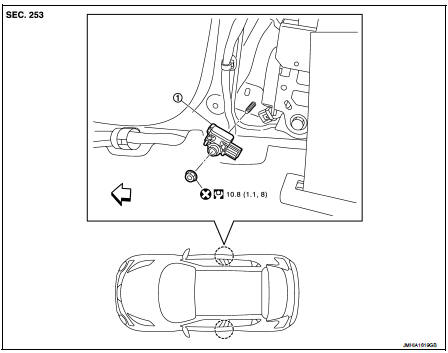
1. Satellite sensor
 : Vehicle front
 : Do not reuse
 : N·m (kg-m, ft-lb)
Removal and Installation
WARNING:
• Before servicing, turn ignition switch OFF, disconnect battery negative
terminal and wait 3 minutes
or more.
• Never use the air tools or electric tools for servicing.
REMOVAL
1. Remove the center pillar lower garnish. Refer to INT-20, "CENTER PILLAR LOWER GARNISH : Removal and Installation".
2. Remove the side air bag (satellite) sensor fixing nut (A), and then pull the side air bag (satellite) sensor (1).
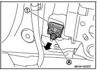
3. Disconnect the harness connector and then remove the side air bag (satellite) sensor.
CAUTION:
• Never impact the side air bag (satellite) sensor.
• Replace the side air bag (satellite) sensor if it has been dropped or sustained an impact.
• Replace the side air bag (satellite) sensor of deployed SRS front side air bag module and deployed SRS side curtain air bag module.
INSTALLATION
Note the following items, and then install in the reverse order of removal.
CAUTION:
• Never use the old fixing nut after removal, replace with the new nut.
• Never damage the harness while installing.
• Always install normally aligning to the cutout hole, because performance of the side air bag (satellite) sensor excessively fluctuates according to the installation position.
• If malfunction is detected by the air bag warning lamp, after repair or replacement of the malfunctioning parts, reset the memory using self-diagnosis or CONSULT-III. Refer to SRC-12, "On Board Diagnosis Function" or SRC-16, "CONSULT-III Function".
• After the work is completed, check that no system malfunction is detected by air bag warning lamp
 Crash zone sensor
Exploded View
1. Crash zone sensor
2. Bracket
: Vehicle front
: Do not reuse
N·m (kg-m, ft-lb)
Removal and Installation
WARNING:
• Before servicing, turn ignition switch OFF, disconnect ...
 Diagnosis sensor unit
Exploded View
1. Diagnosis sensor unit
: Vehicle front
: Do not reuse
: N·m (kg-m, ft-lb)
Removal and Installation
WARNING:
• Before servicing, turn ignition switch OFF, disconnect battery ...
Other materials:
Operation inspection
Work Procedure
The purpose of the operational check is to check that the individual system
operates normally.
Check condition : Engine running at normal operating temperature.
1.CHECK MEMORY FUNCTION
1. Set temperature to 30°C by operating the temperature control dial.
2. Press OFF switch.
...
Operation
Autmatic speed control device (ASCD) : Switch Name and Function
SWITCHES AND INDICATORS
NOTE:
Shared with speed limiter switch.
1. CRUISE indicator lamp
2. SET indicator lamp
3. CANCEL switch
4. Speed limiter MAIN switch
5. ASCD MAIN switch
6. SET / − switch
(SET / COAST)
7. ...
Fog light switch (if so equipped)
To turn the fog lights on, turn the headlight switch to the
position, then turn the switch to the
position. To turn them off, turn the
switch to the OFF position.
The headlights must be on for the fog lights to operate.
When the headlight switch is in the AUTO position, turning the fog lig ...
