Nissan Juke Service and Repair Manual : Diagnosis sensor unit
Exploded View
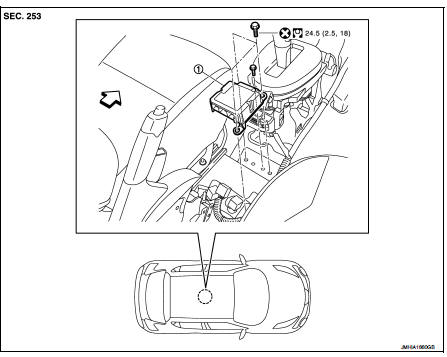
1. Diagnosis sensor unit
 : Vehicle front
 : Do not reuse
 : N·m (kg-m, ft-lb)
Removal and Installation
WARNING:
• Before servicing, turn ignition switch OFF, disconnect battery negative
terminal and wait 3 minutes
or more.
• Before disconnecting the air bag sensor unit harness connector, be sure to disconnect the each harness connector of the air bag module and pre-tensioner seat belt to prevent air bag deployment by static electricity and pre-tensioner seat belt operation.
• Never use the air tools or electric tools for servicing.
• When replacing the air bag diagnosis sensor unit, always check with the parts department for the latest parts information. Installing an incorrect air bag diagnosis sensor unit may or may not cause the air bag warning lamp to illuminate and may cause incorrect deployment of the supplemental air bags and seat belt pre-tensioners in a collision resulting in serious personal injury or death.
REMOVAL
1. Always check the air bag diagnosis sensor unit ECU discriminated number (identification number) using CONSULT-III.
2. Disconnect the each connector of all air bag modules and pre-tensioner seat belts.
3. Remove the center console assembly. Refer to IP-23, "Removal and Installation".
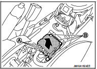
4. Disconnect the diagnosis sensor unit harness connectors (A).
5. Remove the diagnosis sensor unit mounting bolts (B), and then remove the diagnosis sensor unit.
CAUTION:
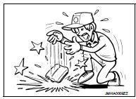
• Never impact the diagnosis sensor unit.
• Replace the diagnosis sensor unit if it has been dropped or sustained an impact.
• Replace the diagnosis sensor unit of deployed SRS air bag and deployed SRS front seat belt pre-tensioner.
INSTALLATION
Note the following items, and then install in the reverse order of removal.
CAUTION:
• Never use the old bolts after removal, replace with the new bolts.
• Never damage the harness while installing.
• If malfunction is detected by the air bag warning lamp, after repair or replacement of the malfunctioning parts, reset the memory using self-diagnosis or CONSULT-III. Refer to SRC-12, "On Board Diagnosis Function" or SRC-16, "CONSULT-III Function".
• After the work is completed, check that no system malfunction is detected by air bag warning lamp.
• After replacing the air bag diagnosis sensor unit, confirm using CONSULT-III that the ECU discriminated number (identification number) of the new replacement air bag sensor unit matches the ECU discriminated number (identification number) of the replaced (old) air bag diagnosis sensor unit.
NOTE:
If the ECU discriminated number of the new replacement air bag diagnosis sensor unit differs from the ECU discriminated number of the replaced air bag diagnosis sensor unit, reconfirm the parts information and verify that the correct air bag diagnosis sensor unit was installed.
 Side air bag (satellite) sensor
Exploded View
1. Satellite sensor
: Vehicle front
: Do not reuse
: N·m (kg-m, ft-lb)
Removal and Installation
WARNING:
• Before servicing, turn ignition switch OFF, disconnect battery nega ...
 Seat belt pre-tensioner
Exploded View
Refer to SB-4, "Exploded View".
Removal and Installation
For removal and installation procedures, refer to SB-5, "SEAT BELT RETRACTOR
: Removal and Installation" ...
Other materials:
Windows
POWER WINDOWS
WARNING
• Make sure that all passengers have their hands, etc. inside the vehicle
while it is in motion and before closing the windows. Use the window lock switch
to prevent unexpected use of the power windows.
• Do not leave children unattended inside the vehicle. They coul ...
Vehicle Security System
The vehicle security system provides visual and audio alarm signals if someone
opens the doors, or lift gate when the system is armed. It is not, however, a motion
detection type system that activates when a vehicle is moved or when a vibration
occurs.
The system helps deter vehicle theft but ...
Engine idle speed too low or unstable
Description
CHART 6: ENGINE IDLE SPEED TOO LOW OR UNSTABLE
Diagnosis Procedure
1.CHECK FUEL
Check that the fuel reservoir is correctly filled and with the right fuel.
>> GO TO 2.
2.CHECK ECM POWER SUPPLY AND GROUND CIRCUIT
Check ECM power supply and ground circuit. Refer to EC-885, ...
