Nissan Juke Service and Repair Manual : Headlamp washer circuit
Component Function Check
1.CHECK HEADLAMP WASHER OPERATION
 CONSULT-III ACTIVE TEST
1. Select тАЬHEAD LAMP WASHERтАЭ of IPDM E/R active test item.
2. With operating the test item, check headlamp operation.
On :Headlamp washer ON operation Off :Stop the headlamp washer.
Is headlamp washer operation normally? YES >> Headlamp washer circuit is normal.
NO >> Refer to WW-50, "Diagnosis Procedure".
Diagnosis Procedure
1.CHECK HEADLAMP WASHER FUSIBLE LINK
1. Turn the ignition switch OFF.
2. Check that the headlamp washer 30A fusible link (#L) is not fusing.
Is the fusible link fusing? YES >> Replace the fusible link after repairing the applicable circuit.
NO >> GO TO 2.
2.CHECK HEADLAMP WASHER RELAY POWER SUPPLY
1. Remove headlamp washer relay.
2. Check voltage between headlamp washer relay harness connector and ground.
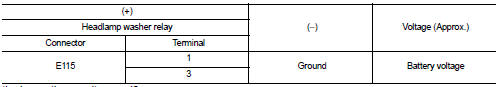
Is the inspection result normal? YES >> GO TO 3.
NO >> Repair harnesses or connectors.
3.CHECK HEADLAMP WASHER RELAY
Check headlamp washer relay. Refer to WW-49, "Component Inspection".
Is the headlamp washer relay normal? YES >> GO TO 4.
NO >> Replace headlamp washer relay.
4.CHECK HEADLAMP WASHER RELAY CONTROL SIGNAL
 CONSULT-III ACTIVE TEST
1. Turn the ignition switch OFF.
2. Install headlamp washer relay.
3. Turn the ignition switch ON.
4. Select тАЬHEAD LAMP WASHERтАЭ of IPDM E/R active test item.
5. With operating the test item, check voltage between IPDM E/R harness connector and ground.
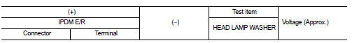

Is the inspection result normal? YES >> GO TO 7.
Fixed at 0 V >> GO TO 5.
Fixed at battery voltage >>Replace IPDM E/R.
5.CHECK HEADLAMP WASHER RELAY CONTROL SIGNAL OPEN CIRCUIT
1. Turn the ignition switch OFF.
2. Remove headlamp washer relay.
3. Disconnect IPDM E/R harness connector.
4. Check continuity between IPDM E/R harness connector and headlamp washer relay harness connector.
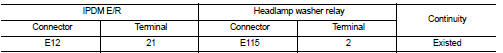
Is the inspection result normal? YES >> GO TO 6.
NO >> Repair the harnesses or connectors.
6.CHECK HEADLAMP WASHER RELAY CONTROL SIGNAL SHORT CIRCUIT
Check continuity between IPDM E/R harness connector and ground.
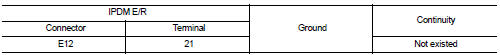
Is the inspection result normal? YES >> Repair the harnesses or connectors.
NO >> Replace IPDM E/R.
7.CHECK HEADLAMP WASHER PUMP OPEN CIRCUIT
1. Turn the ignition switch OFF.
2. Remove headlamp washer relay.
3. Disconnect headlamp washer pump connector.
4. Check continuity between headlamp washer relay harness connector and headlamp washer pump harness connector.
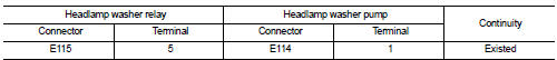
Is the inspection result normal? YES >> GO TO 8.
NO >> Repair the harnesses or connectors.
8.CHECK HEADLAMP WASHER PUMP (GND) OPEN CIRCUIT
Check continuity headlamp washer pump harness connector and ground.
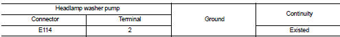
Is the inspection result normal? YES >> Replace headlamp washer pump.
NO >> Repair the harnesses or connectors.
 Headlamp washer relay
Component Inspection
1.CHECK HEADLAMP WASHER RELAY
1. Turn the ignition switch OFF.
2. Remove headlamp washer relay.
3. Apply battery voltage to headlamp washer relay between terminals 1 and 2.
4 ...
 Wiper and washer system
Wiring Diagram - WIPER AND WASHER SYSTEM -
For connector terminal arrangements, harness layouts, and alphabets in a
(option abbreviation; if not
described in wiring diagram), refer to GI-12, " ...
Other materials:
Checking engine oil level
1. Park the vehicle on a level surface and apply the parking brake.
2. Run the engine until it reaches operating temperature.
3. Turn off the engine. Wait more than 10 minutes for the oil to drain back into
the oil pan.
4. Remove the dipstick and wipe it clean.
Reinsert it all the way.
5. R ...
I-BSI system operation
Side Indicator Light
Blind Spot Warning (BSW) indicator
Intelligent Blind Spot Intervention (I-BSI) indicator
Dynamic driver assistance switch (models without ProPILOT Assist)
ProPILOT Assist switch (models with ProPILOT Assist)
...
General Precautions
WARNING:
When replacing fuel line parts, be sure to observe the following.
тАв Put a тАЬCAUTION: FLAMMABLEтАЭ sign in the workshop.
тАв Be sure to work in a well ventilated area and furnish workshop with a CO2 fire
extinguisher.
тАв Never smoke while servicing fuel system. Keep open flames a ...
