Nissan Juke Service and Repair Manual : Wiper and washer system
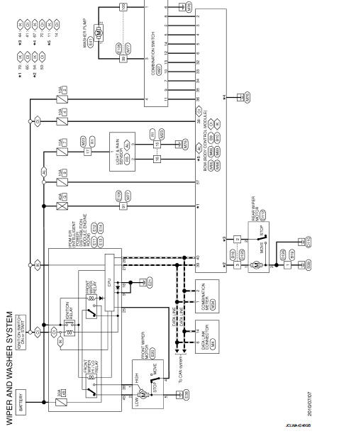
Wiring Diagram - WIPER AND WASHER SYSTEM -
For connector terminal arrangements, harness layouts, and alphabets in a
 (option abbreviation; if not
described in wiring diagram), refer to GI-12, "Connector Information/Explanation
of Option Abbreviation".
 Headlamp washer circuit
Component Function Check
1.CHECK HEADLAMP WASHER OPERATION
CONSULT-III ACTIVE TEST
1. Select “HEAD LAMP WASHER” of IPDM E/R active test item.
2. With operating the test item, check headlamp op ...
 Headlamp washer system
Wiring Diagram - HEADLAMP WASHER SYSTEM -
For connector terminal arrangements, harness layouts, and alphabets in a
(option abbreviation; if not
described in wiring diagram), refer to GI-12, "C ...
Other materials:
Refrigerant pressure sensor
Component Function Check
1.CHECK REFRIGERANT PRESSURE SENSOR OVERALL FUNCTION
1. Start engine and warm it up to normal operating temperature.
2. Turn A/C switch and blower fan switch ON.
3. Check the voltage between ECM harness connector and ground.]
Is the inspection result normal?
YES > ...
Clock (if so equipped)
The digital clock (in the audio unit) displays time when the ignition switch
is in the ACC or ON position. The clock ON or OFF mode can be selected. For details
of the digital clock in the NAVIGATION SYSTEM, refer to “Clock” .
If the power supply is disconnected, the clock will not indicate ...
Windshield wiper blades
Cleaning
If your windshield fails to clear properly after utilizing the washer system, or if you notice the wiper blades "chattering" and skipping across the glass during operation, this is often a sign that road film, wax, or other environmental contaminants have accumulated on the rubber blad ...
