Nissan Juke Service and Repair Manual : Refrigerant pressure sensor
Component Function Check
1.CHECK REFRIGERANT PRESSURE SENSOR OVERALL FUNCTION
1. Start engine and warm it up to normal operating temperature.
2. Turn A/C switch and blower fan switch ON.
3. Check the voltage between ECM harness connector and ground.]
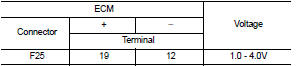
Is the inspection result normal? YES >> INSPECTION END
NO >> Proceed to EC-423, "Diagnosis Procedure".
Diagnosis Procedure
1.CHECK REFRIGERANT PRESSURE SENSOR POWER SUPPLY
1. Turn ignition OFF.
2. Disconnect refrigerant pressure sensor harness connector.
3. Turn ignition switch ON.
4. Check the voltage between refrigerant pressure sensor harness connector and ground.
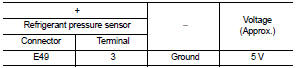
Is the inspection result normal? YES >> GO TO 3.
NO >> GO TO 2.
2.CHECK REFRIGERANT PRESSURE SENSOR POWER SUPPLY CIRCUIT
1. Turn ignition switch OFF.
2. Disconnect ECM harness connector.
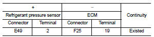
3. Check the continuity between refrigerant pressure sensor harness connector and ECM harness connector.
4. Also check harness for short to ground.
Is the inspection result normal? YES >> Perform the trouble diagnosis for power supply circuit.
NO >> Repair or replace error-detected parts.
3.CHECK REFRIGERANT PRESSURE SENSOR GROUND
1. Turn ignition switch OFF.
2. Disconnect ECM harness connector.
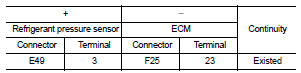
3. Check the continuity between refrigerant pressure sensor harness connector and ECM harness connector.
4. Also check harness for short to power.
Is the inspection result normal? YES >> GO TO 4.
NO >> Repair or replace error-detected parts.
4.CHECK REFRIGERANT PRESSURE SENSOR INPUT SIGNAL CIRCUIT
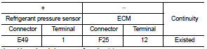
1. Check the continuity between ECM harness connector and refrigerant pressure sensor harness connector.
2. Also check harness for short to ground and to power.
Is the inspection result normal? YES >> GO TO 5.
NO >> Repair or replace error-detected parts.
5.CHECK INTERMITTENT INCIDENT.
Perform GI-42, "Intermittent Incident".
Is the inspection result normal? YES >> Replace refrigerant pressure sensor. Refer to HAC-96, "Exploded View".
NO >> Repair or replace error-detected parts.
 Cooling fan
Component Function Check
1.CHECK COOLING FAN FUNCTION
With CONSULT-III
1. Turn ignition switch ON.
2. Perform ÔÇťFAN DUTY CONTROLÔÇŁ in ÔÇťACTIVE TESTÔÇŁ mode of ÔÇťENGINEÔÇŁ using
CONSULT-III.
...
 Brake pedal position switch
Component Function Check
1.CHECK BRAKE PEDAL POSITION SWITCH FUNCTION
With CONSULT-III
1. Turn ignition switch ON.
2. Select ÔÇťBRAKE SW1ÔÇŁ in ÔÇťDATA MONITORÔÇŁ mode of ÔÇťENGINEÔÇŁ using CONSUL ...
Other materials:
Electrical load signal
Description
The electrical load signal (Headlamp switch signal, rear window defogger
switch signal, etc.) is transferred via
the CAN communication line.
Component Function Check
1.CHECK REAR WINDOW DEFOGGER SWITCH FUNCTION
With CONSULT-III
1. Turn ignition switch ON.
2. Select ÔÇťDATA MONIT ...
B1042, B1043, B1044, B1045, B1046, B1047 diagnosis sensor unit
DTC Logic
DTC DETECTION LOGIC
DTC CONFIRMATION PROCEDURE
1.CHECK SELF-DIAG RESULT
With CONSULT-III
1. Turn ignition switch ON.
2. Perform ÔÇťSelf Diagnostic ResultÔÇŁ mode of ÔÇťAIR BAGÔÇŁ using CONSULT-III.
Without CONSULT-III
1. Turn ignition switch ON.
2. Check the air bag warning la ...
P2127, P2128 APP sensor
DTC Logic
DTC DETECTION LOGIC
DTC CONFIRMATION PROCEDURE
1.PRECONDITIONING
If DTC Confirmation Procedure has been previously conducted, always perform
the following procedure
before conducting the next test.
1. Turn ignition switch OFF and wait at least 10 seconds.
2. Turn ignition swit ...
