Nissan Juke Service and Repair Manual : Brake pedal position switch
Component Function Check
1.CHECK BRAKE PEDAL POSITION SWITCH FUNCTION
 With CONSULT-III
1. Turn ignition switch ON.
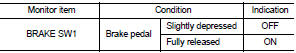
2. Select ŌĆ£BRAKE SW1ŌĆØ in ŌĆ£DATA MONITORŌĆØ mode of ŌĆ£ENGINEŌĆØ using CONSULT-III.
3. Check ŌĆ£BRAKE SW1ŌĆØ indication as per the following conditions.
 Without CONSULT-III
1. Turn ignition switch ON.
2. Check the voltage between ECM harness connector terminals as per the following.
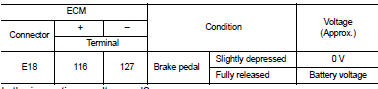
Is the inspection result normal? YES >> INSPECTION END
NO >> Proceed to EC-425, "Diagnosis Procedure".
Diagnosis Procedure
1.CHECK BRAKE PEDAL POSITION SWITCH POWER SUPPLY
1. Turn ignition switch OFF.
2. Disconnect brake pedal position switch harness connector.
3. Turn ignition switch ON.
4. Check the voltage between brake pedal position switch harness connector and ground.
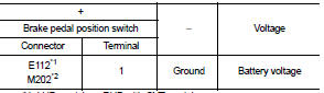
*1: LHD models or RHD with CVT models *2: RHD with M/T models
Is the inspection result normal? YES >> GO TO 2.
NO >> Perform the trouble diagnosis for power supply circuit.
2.CHECK BRAKE PEDAL POSITION SWITCH INPUT SIGNAL CIRCUIT
1. Turn ignition switch OFF.
2. Disconnect ECM harness connector.
3. Check the continuity between brake pedal position switch harness connector and ECM harness connector.
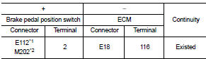
*1: LHD models or RHD with CVT models *2: RHD with M/T models
4. Also check harness for short to ground and to power.
Is the inspection result normal? YES >> GO TO 3.
NO >> Repair or replace error-detected parts.
3.CHECK BRAKE PEDAL POSITION SWITCH
Check the brake pedal position switch. Refer to EC-426, "Component Inspection (Brake Pedal Position Switch)" Is the inspection result normal? YES >> Check intermittent incident. Refer to GI-42, "Intermittent Incident".
NO >> Replace brake pedal position switch. Refer to BR-20, "Exploded View" (LHD) or BR-88, "Exploded View" (RHD)
Component Inspection (Brake Pedal Position Switch)
1.CHECK BRAKE PEDAL POSITION SWITCH-I
1. Turn ignition switch OFF.
2. Disconnect brake pedal position harness connector.
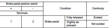
3. Check the continuity between brake pedal position switch terminals as per the following conditions.
Is the inspection result normal? YES >> INSPECTION END
NO >> GO TO 2.
2.CHECK BRAKE PEDAL POSITION SWITCH-II
1. Adjust brake pedal position switch installation. Refer to BR-9, "Inspection and Adjustment" (LHD) or BR- 77, "Inspection and Adjustment" (RHD).
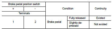
2. Check the continuity between brake pedal position switch terminals as per the following conditions.
Is the inspection result normal? YES >> INSPECTION END
NO >> Replace brake pedal position switch. Refer to BR-20, "Exploded View" (LHD) or BR-88, "Exploded View" (RHD).
 Refrigerant pressure sensor
Component Function Check
1.CHECK REFRIGERANT PRESSURE SENSOR OVERALL FUNCTION
1. Start engine and warm it up to normal operating temperature.
2. Turn A/C switch and blower fan switch ON.
3. Check ...
 Clutch pedal position switch
Component Function Check
1.CHECK FOR CLUTCH PEDAL POSITION SWITCH FUNCTION
1. Turn ignition switch ON.
2. Check the voltage between ECM harness connector and ground.
Is the inspection result nor ...
Other materials:
Cooler pipe and hose
Exploded View
1. A/C unit assembly
2. O-ring
3. High-pressure pipe
4. Condenser
5. Low-pressure flexible hose
6. O-ring
7. Compressor
8. O-ring
9. High-pressure flexible hose
: Do not reuse
: N┬Ęm (kg-m, in-lb)
: N┬Ęm (kg-m, ft-lb)
High-pressure flexible hose : Removal and Insta ...
Reservoir tank cap
Inspection
ŌĆó Check valve seat of reservoir tank cap.
- Check if valve seat (A) is swollen to the extent that the edge of the
metal plunger (B) cannot be seen when watching it vertically from
the top.
- Check if valve seat has no soil and damage.
ŌĆó Pull negative-pressure valve to open i ...
B2627 outside antenna
DTC Logic
DTC DETECTION LOGIC
DTC CONFIRMATION PROCEDURE
1.PERFORM DTC CONFIRMATION PROCEDURE
1. Disconnect outside key antenna (passenger side) connector.
2. Perform ŌĆ£INTELLIGENT KEYŌĆØ Self Diagnostic Result.
Is outside key antenna DTC detected?
YES >> Refer to DLK-238, "Di ...
