Nissan Juke Service and Repair Manual : Clutch pedal position switch
Component Function Check
1.CHECK FOR CLUTCH PEDAL POSITION SWITCH FUNCTION
1. Turn ignition switch ON.
2. Check the voltage between ECM harness connector and ground.
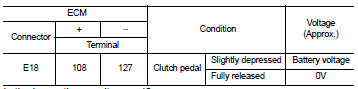
Is the inspection result normal? YES >> INSPECTION END.
NO >> Proceed to EC-427, "Diagnosis Procedure".
Diagnosis Procedure
1.CHECK CLUTCH PEDAL POSITION INPUT SIGNAL
1. Turn ignition switch OFF.
2. Disconnect clutch pedal position switch harness connector.
3. Turn ignition switch ON.
4. Check the voltage between clutch pedal position switch harness connector and ground.
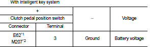
*1: LHD models
*2: RHD models
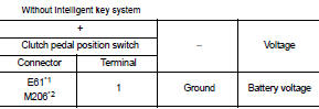
*1: LHD models
*2: RHD models
Is the inspection result normal? YES >> GO TO 3.
NO >> GO TO 2.
2.CHECK CLUTCH PEDAL POSITION SWITCH INPUT SIGNAL CIRCUIT
1. Turn ignition switch OFF.
2. Disconnect ECM harness connectors.
3. Check the continuity between clutch pedal position switch harness connector and ECM harness connector.
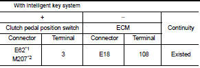
*1: LHD models
*2: RHD models
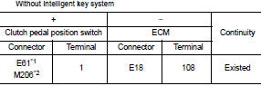
*1: LHD models
*2: RHD models
4. Also check harness for short to ground and to power.
Is the inspection result normal? YES >> Perform the trouble diagnosis for power supply circuit.
NO >> Repair or replace error-detected parts.
3.CHECK CLUTCH PEDAL POSITION SWITCH GROUND CIRCUIT
1. Turn ignition switch OFF.
2. Disconnect ECM harness connectors.
3. Check the continuity between clutch pedal position switch harness connector and ground
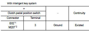
*1: LHD models
*2: RHD models
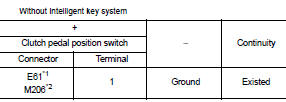
*1: LHD models
*2: RHD models
4. Also check harness for short to power.
Is the inspection result normal? YES >> GO TO 4.
NO >> Repair or replace error-detected parts.
4.CHECK CLUTCH PEDAL POSITION SWITCH
Check the clutch pedal position switch. Refer to EC-429, "Component Inspection".
Is the inspection result normal?
YES >> Check intermittent incident. Refer to GI-42, "Intermittent Incident".
NO >> Replace clutch pedal position switch. Refer to CL-16, "LHD : Exploded View" (LHD models) or CL- 18, "RHD : Exploded View" (RHD models).
Component Inspection
1.CHECK CLUTCH PEDAL POSITION SWITCH-I
1. Turn ignition switch OFF.
2. Disconnect clutch pedal position switch harness connector.
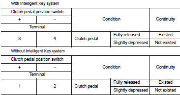
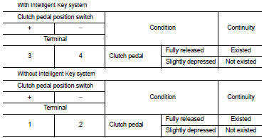
3. Check the continuity between clutch pedal position switch terminals as per the following conditions.
Is the inspection result normal? YES >> INSPECTION END
NO >> GO TO 2.
2.CHECK CLUTCH PEDAL POSITION SWITCH-II
1. Adjust clutch pedal position switch installation. Refer to CL-17, "LHD : Inspection and Adjustment" (LHD models) or CL-19, "RHD : Inspection and Adjustment" (RHD models).
2. Check the continuity between clutch pedal position switch terminals as per the following conditions.
Is the inspection result normal? YES >> INSPECTION END
NO >> Replace clutch pedal position switch. Refer to CL-16, "LHD : Exploded View" (LHD models) or CL- 18, "RHD : Exploded View" (RHD models).
 Brake pedal position switch
Component Function Check
1.CHECK BRAKE PEDAL POSITION SWITCH FUNCTION
With CONSULT-III
1. Turn ignition switch ON.
2. Select ÔÇťBRAKE SW1ÔÇŁ in ÔÇťDATA MONITORÔÇŁ mode of ÔÇťENGINEÔÇŁ using CONSUL ...
 ASCD main switch
Component Function Check
1.CHECK ASCD MAIN SWITCH FUNCTION
With CONSULT-III
1. Turn ignition switch ON.
2. Select ÔÇťMAIN SWÔÇŁ in ÔÇťDATA MONITORÔÇŁ mode of ÔÇťENGINEÔÇŁ using CONSULT-III.
3. Ch ...
Other materials:
Liquid Gasket
REMOVAL OF LIQUID GASKET
ÔÇó After removing mounting nuts and bolts, separate the mating surface
using the seal cutter [SST: KV10111100] (A) and remove old
liquid gasket sealing.
CAUTION:
Be careful not to damage the mating surfaces.
ÔÇó Tap the seal cutter [SST: KV10111100] to insert it (B) ...
On Board Diagnostic (OBD) System of Engine and CVT
The ECM has an on board diagnostic system. It will light up the malfunction
indicator lamp (MIL) to warn the
driver of a malfunction causing emission deterioration.
CAUTION:
ÔÇó Be sure to turn the ignition switch OFF and disconnect the negative battery
cable before any repair
or inspectio ...
System
Can communication system
CAN COMMUNICATION SYSTEM : System Description
CAN (Controller Area Network) is a serial communication line for real time
application. It is an on-vehicle multiplex
communication line with high data communication speed and excellent error
detection ability. Many electr ...
