Nissan Juke Service and Repair Manual : ASCD main switch
Component Function Check
1.CHECK ASCD MAIN SWITCH FUNCTION
 With CONSULT-III
1. Turn ignition switch ON.
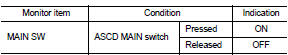
2. Select “MAIN SW” in “DATA MONITOR” mode of “ENGINE” using CONSULT-III.
3. Check “MAIN SW” indication as per the following condition.
 Without CONSULT-III
1. Turn ignition switch ON.
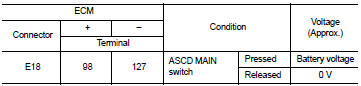
2. Check the voltage between ECM harness connector and ground as per the following conditions.
Is the inspection result normal? YES >> INSPECTION END
NO >> Proceed to EC-430, "Diagnosis Procedure".
Diagnosis Procedure
1.CHECK ASCD MAIN SWITCH POWER SUPPLY
1. Turn ignition switch OFF.
2. Disconnect combination switch (spiral cable) harness connector.
3. Turn ignition switch ON.
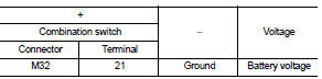
4. Check the voltage between combination switch harness connector and ground.
Is the inspection result normal? YES >> GO TO 2.
NO >> Perform the trouble diagnosis for power supply circuit.
2.CHECK ASCD MAIN SWITCH INPUT SIGNAL CIRCUIT
1. Turn ignition switch OFF.
2. Disconnect ECM harness connector.
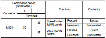
3. Check the continuity between ECM harness connector and combination switch harness connector.
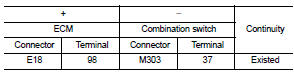
4. Also check harness for short to ground and to power.
Is the inspection result normal? YES >> GO TO 3.
NO >> Repair or replace error-detected parts.
3.CHECK ASCD STEERING SWITCH
Check the ASCD steering switch. Refer to EC-431, "Component Inspection".
Is the inspection result normal? YES >> Check intermittent incident. Refer to GI-42, "Intermittent Incident".
NO >> Replace ASCD steering switch. Refer to ST-9, "Exploded View".
Component Inspection
1.CHECK ASCD STEERING SWITCH-I
1. Disconnect combination switch (spiral cable) harness connector.
2. Check the continuity between combination switch harness connector terminals as per the following conditions.
Is the inspection result normal? YES >> INSPECTION END
NO >> Replace ASCD steering switch. Refer to ST-9, "Exploded View".
2.CHECK ASCD STEERING SWITCH
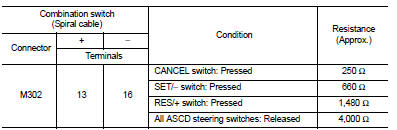
1. Disconnect combination switch (spiral cable) harness connector.
2. Check the resistance between combination switch harness connector terminals as per the following conditions.
Is the inspection result normal? YES >> INSPECTION END
NO >> Replace ASCD steering switch. Refer to ST-9, "Exploded View".
 Clutch pedal position switch
Component Function Check
1.CHECK FOR CLUTCH PEDAL POSITION SWITCH FUNCTION
1. Turn ignition switch ON.
2. Check the voltage between ECM harness connector and ground.
Is the inspection result nor ...
 SPEED LIMITER MAIN SWITCH
Component Function Check
1.CHECK SPEED LIMITER MAIN SWITCH FUNCTION
With CONSULT-III
1. Turn ignition switch ON.
2. Select “SL MAIN SW” in “DATA MONITOR” mode of “ENGINE” using CONSULT ...
Other materials:
U1010 control unit (CAN)
Description
CAN (Controller Area Network) is a serial communication line for real time
application. It is an on-vehicle multiplex
communication line with high data communication speed and excellent error
detection ability. Many electronic
control units are equipped onto a vehicle, and each co ...
Engine idle speed too low or unstable
Description
CHART 6: ENGINE IDLE SPEED TOO LOW OR UNSTABLE
Diagnosis Procedure
1.CHECK FUEL
Check that the fuel reservoir is correctly filled and with the right fuel.
>> GO TO 2.
2.CHECK ECM POWER SUPPLY AND GROUND CIRCUIT
Check ECM power supply and ground circuit. Refer to EC-885, ...
Door motor
Exploded View
LEFT SIDE
1. A/C unit assembly
2. Intake door lever
3. Intake door motor
4. Air mix door motor
5. Upper air mix door rod
6. Upper air mix door lever
7. Lower air mix door lever
8. Lower air mix door rod
RIGHT SIDE
1. A/C unit assembly
2. Main link
3. Sub defrost ...
