Nissan Juke Service and Repair Manual : B1118, B1119 satellite sensor LH
DTC Logic
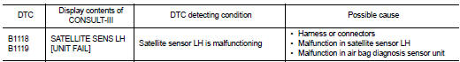
DTC DETECTION LOGIC
DTC CONFIRMATION PROCEDURE
1.CHECK SELF-DIAG RESULT
 With CONSULT-III
1. Turn ignition switch ON.
2. Perform ŌĆ£Self Diagnostic ResultŌĆØ mode of ŌĆ£AIR BAGŌĆØ using CONSULT-III.
 Without CONSULT-III
1. Turn ignition switch ON.
2. Check the air bag warning lamp status. Refer to SRC-12, "On Board Diagnosis Function".
NOTE
:
SRS does not enter the diagnosis mode if no malfunction is detected in the user
mode.
Is malfunctioning part detected? YES >> Refer to SRC-88, "Diagnosis Procedure".
NO >> INSPECTION END
Diagnosis Procedure
WARNING:
ŌĆó Before servicing, turn ignition switch OFF, disconnect battery negative
terminal, and wait at least 3
minutes or more. (To discharge backup capacitor.)
ŌĆó Never use unspecified tester or other measuring device.
1.CHECK HARNESS CONNECTOR
Check the harness connector.
Is the inspection result normal? YES >> GO TO 2.
NO >> Replace harness connector.
2.CHECK WIRING HARNESS
Check the wiring harness externals.
Is the inspection result normal? YES >> GO TO 3.
NO >> Replace wiring harness.
3.REPLACE SATELLITE SENSOR
1. Replace satellite sensor LH. Refer to SR-28, "Removal and Installation".
2. Perform DTC confirmation procedure. Refer to SRC-88, "DTC Logic" Is DTC detected? YES >> GO TO 4.
NO >> INSPECTION END
4.REPLACE AIR BAG DIAGNOSIS SENSOR UNIT
1. Replace air bag diagnosis sensor unit. Refer to SR-30, "Removal and Installation".
2. Perform DTC confirmation procedure. Refer to SRC-88, "DTC Logic".
Is DTC detected? YES >> GO TO 1.
NO >> INSPECTION END
 B1116 satellite sensor RH
DTC Logic
DTC DETECTION LOGIC
DTC CONFIRMATION PROCEDURE
1.CHECK SELF-DIAG RESULT
With CONSULT-III
1. Turn ignition switch ON.
2. Perform ŌĆ£Self Diagnostic ResultŌĆØ mode of ŌĆ£AIR BAGŌĆØ usi ...
 B1120 satellite sensor LH
DTC Logic
DTC DETECTION LOGIC
DTC CONFIRMATION PROCEDURE
1.CHECK SELF-DIAG RESULT
With CONSULT-III
1. Turn ignition switch ON.
2. Perform ŌĆ£Self Diagnostic ResultŌĆØ mode of ŌĆ£AIR BAGŌĆØ usi ...
Other materials:
Intelligent Keys (if so equipped)
Your vehicle can only be driven with the Intelligent Keys which are registered
to your vehicleŌĆÖs Intelligent Key system components and NISSAN Vehicle Immobilizer
System components.
As many as 4 Intelligent Keys can be registered and used with one vehicle. The
new keys must be registered by ...
Headlamp washer circuit
Component Function Check
1.CHECK HEADLAMP WASHER OPERATION
CONSULT-III ACTIVE TEST
1. Select ŌĆ£HEAD LAMP WASHERŌĆØ of IPDM E/R active test item.
2. With operating the test item, check headlamp operation.
On :Headlamp washer ON operation
Off :Stop the headlamp washer.
Is headlamp washer opera ...
Maintenance precautions
When performing any inspection or maintenance work on your vehicle, always take
care to prevent serious accidental injury to yourself or damage to the vehicle.
The following are general precautions which should be closely observed.
WARNING
ŌĆó Park the vehicle on a level surface, apply t ...
