Nissan Juke Service and Repair Manual : Battery
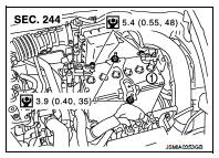
Exploded View
1 : Battery fix frame
 :N·m (kg-m, in-lb)
Removal and Installation
REMOVAL
1. Disconnect the battery cable from the negative terminal.
CAUTION:
When disconnecting, disconnect the battery cable from the negative terminal
first.
2. Remove cover of battery positive terminal.
3. Disconnect the battery cable from the positive terminal.
4. Remove battery fix frame mounting nuts and battery fix frame.
5. Remove battery.
INSTALLATION
Install in the reverse order of removal.
CAUTION:
To install the battery, carefully read the following instructions.
• When connecting, connect the battery cable to the positive terminal first.
• After connecting battery cables, ensure that they are tightly clamped to battery terminals for good contact.
• Check battery terminal for poor connection caused by corrosion.
Reset electronic systems as necessary. Refer to GI-54, "ADDITIONAL SERVICE WHEN REMOVING BATTERY NEGATIVE TERMINAL : Required Procedure After Battery Disconnection".

 Battery terminal with fusible link
Exploded View
1 : Battery terminal with fusible link
2 : Harness connector
: N·m (kg-m, ft-lb)
Removal and Installation
REMOVAL
1. Disconnect the battery cable from the negative terminal.
2. ...
Other materials:
The EV (Electric Vehicle) system
The Nissan Leaf is an advanced electric vehicle, offering a driving experience that differs significantly from traditional internal combustion engines. Because of these unique operating characteristics, it is essential to familiarize yourself with this owner's manual. The primary distinction is that ...
Impossible to shut off engine
Description
CHART 4: IMPOSSIBLE TO SHUT OFF ENGINE
Diagnosis Procedure
1.CHECK ECM POWER SUPPLY AND GROUND CIRCUIT
Check ECM power supply and ground circuit. Refer to EC-885, "Diagnosis
Procedure".
Is the inspection result normal?
YES >> GO TO 2.
NO >> Repair or re ...
Difference between predicted and
actual distances
The superimposed guidelines displayed on the monitor panel and their indicated contact points on the ground are calibrated exclusively for approximate driver reference. Physical obstacles located on steep uphill gradients, downhill slopes, or objects projecting horizontally into mid-air will actuall ...
