Nissan Juke Service and Repair Manual : B1116 satellite sensor RH
DTC Logic
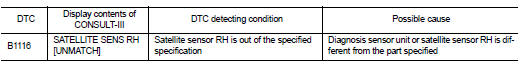
DTC DETECTION LOGIC
DTC CONFIRMATION PROCEDURE
1.CHECK SELF-DIAG RESULT
 With CONSULT-III
1. Turn ignition switch ON.
2. Perform ÔÇťSelf Diagnostic ResultÔÇŁ mode of ÔÇťAIR BAGÔÇŁ using CONSULT-III.
 Without CONSULT-III
1. Turn ignition switch ON.
2. Check the air bag warning lamp status. Refer to SRC-12, "On Board Diagnosis Function".
NOTE
:
SRS does not enter the diagnosis mode if no malfunction is detected in the user
mode.
Is malfunctioning part detected? YES >> Refer to SRC-87, "Diagnosis Procedure".
NO >> INSPECTION END
Diagnosis Procedure
WARNING:
ÔÇó Before servicing, turn ignition switch OFF, disconnect battery negative
terminal, and wait at least 3
minutes or more. (To discharge backup capacitor.)
ÔÇó Never use unspecified tester or other measuring device.
1.CHECK HARNESS CONNECTOR
Check the harness connector.
Is the inspection result normal? YES >> GO TO 2.
NO >> Replace harness connector.
2.CHECK WIRING HARNESS
Check the wiring harness externals.
Is the inspection result normal? YES >> GO TO 3.
NO >> Replace wiring harness.
3.REPLACE SATELLITE SENSOR
1. Replace satellite sensor RH. Refer to SR-28, "Removal and Installation".
2. Perform DTC confirmation procedure. Refer to SRC-87, "DTC Logic".
Is DTC detected? YES >> GO TO 4.
NO >> INSPECTION END
4.REPLACE AIR BAG DIAGNOSIS SENSOR UNIT
1. Replace air bag diagnosis sensor unit. Refer to SR-30, "Removal and Installation".
2. Perform DTC confirmation procedure. Refer to SRC-87, "DTC Logic".
Is DTC detected? YES >> GO TO 1.
NO >> INSPECTION END
 B1115 satellite sensor RH
DTC Logic
DTC DETECTION LOGIC
DTC CONFIRMATION PROCEDURE
1.CHECK SELF-DIAG RESULT
With CONSULT-III
1. Turn ignition switch ON.
2. Perform ÔÇťSelf Diagnostic ResultÔÇŁ mode of ÔÇťAIR BAGÔÇŁ usi ...
 B1118, B1119 satellite sensor LH
DTC Logic
DTC DETECTION LOGIC
DTC CONFIRMATION PROCEDURE
1.CHECK SELF-DIAG RESULT
With CONSULT-III
1. Turn ignition switch ON.
2. Perform ÔÇťSelf Diagnostic ResultÔÇŁ mode of ÔÇťAIR BAGÔÇŁ usi ...
Other materials:
Environmental factors influence the rate of corrosion
Moisture
Accumulation of sand, dirt and water on the vehicle body underside can accelerate
corrosion.
Wet floor coverings will not dry completely inside the vehicle, and should be
removed for drying to avoid floor panel corrosion.
Relative humidity
Corrosion will be accelerated in areas of h ...
Back door
Exploded View
REMOVAL
1. Back door weather-strip
2. Back door stay
3. Back door stay lower bracket
4. Bumper rubber
5. Back door striker
6. Back door panel
7. Back door hinge
8. Hole cover
A : Center mark
B : Seam
: Do not reuse
: Body grease
Back door assembly
BACK DOOR ASSEMB ...
Front wiper motor hi circuit
Component Function Check
1.CHECK FRONT WIPER HI OPERATION
CONSULT-III ACTIVE TEST
1. Select ÔÇťFRONT WIPERÔÇŁ of IPDM E/R active test item.
2. With operating the test item, check front wiper operation.
Hi : Front wiper (HI) operation
Off : Stop the front wiper
Is front wiper (HI) operation no ...
