Nissan Juke Service and Repair Manual : General Precautions
Always use a 12 volt battery as power source.
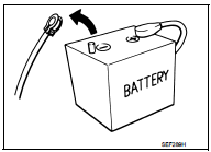
Do not attempt to disconnect battery cables while engine is running.
Before connecting or disconnecting the ECM harness connector, turn ignition switch OFF, wait 3 minutes and disconnect battery negative cable. Failure to do so may damage the ECM because battery voltage is applied to ECM even if ignition switch is turned OFF.
Before removing parts, turn ignition switch OFF and then disconnect battery negative cable.

Do not disassemble ECM.

When connecting ECM harness connector, fasten (A) it securely with levers (1) as far as they will go as shown in the figure.
- ECM (2)
- Loosen (B)

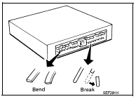
When connecting or disconnecting pin connectors into or from ECM, take care not to damage pin terminals (bend or break).
Make sure that there are not any bends or breaks on ECM pin terminal, when connecting pin connectors.
Securely connect ECM harness connectors.
A poor connection can cause an extremely high (surge) voltage to develop in coil and condenser, thus resulting in damage to IC's.

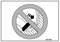
Keep engine control system harness at least 10cm (4 in) away from adjacent harness, to prevent engine control system malfunctions due to receiving external noise, degraded operation of IC's, etc.
Keep engine control system parts and harness dry.
Handle mass air flow sensor carefully to avoid damage.
Do not disassemble mass air flow sensor.
Do not clean mass air flow sensor with any type of detergent.
Even a slight leak in the air intake system can cause serious incidents.
Do not shock or jar the camshaft position sensor, crankshaft position sensor.
When measuring ECM signals with a circuit tester, never allow the two tester probes to contact.
Accidental contact of probes will cause a short circuit and damage the ECM power transistor.
Do not use ECM ground terminals when measuring input/output voltage. Doing so may result in damage to the ECM's transistor.
Use a ground other than ECM terminals, such as the ground.
Do not disassemble fuel pump.
If NG, take proper action.
Do not disassemble fuel injector.
If NG, replace fuel injector.

Do not depress accelerator pedal when staring.
Immediately after staring, do not rev up engine unnecessarily.
Do not rev up engine just prior to shutdown.

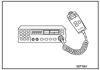
When installing C.B. ham radio or a mobile phone, be sure to observe the following as it may adversely affect electronic control systems depending on installation location.
- Keep the antenna as far as possible from the electronic control units.
- Keep the antenna feeder line more than 20 cm (8 in) away from the harness of electronic controls.
Do not let them run parallel for a long distance.
- Adjust the antenna and feeder line so that the standingwave radio can be kept smaller.
- Be sure to ground the radio to vehicle body.

Cylinder NO.1 is at the flywheel end.
-1: Crankshaft pulley

ENGINE RUNNING
No work should be carried out on the hydraulic system while engine is running.
Remember that fuel pressure values in hydraulic circuit can reach up to 1,600 bar.
Keep hands or face (particularly eyes) out of any high pressure leak.
Recall that fuel is dangerous for health.
FUEL RAIL PRESSURE SENSOR
Under warranty, do not remove the fuel rail pressure sensor from the rail.
Do not try to measure the resistance of the fuel rail pressure sensor. This test is destructive for the internal components.
FUEL INJECTOR
Fuel injectors are driven by over 100V.
FUEL injector electronics are polarised. In case of intervention on wiring harness, do not invertwires. It is destructive for the piezo components.
Do not drive the fuel injectors if their body is not connected to the battery ground (risk ofelectrostatic discharge). For instance, fuel injector body have to be in contact with cylinder.
Piezo fuel injector connector must not be unplugged while engine is running. Risk of majordamage to the engine (fuel injector could stay opened).
 On Board Diagnostic (OBD) System of Engine
The ECM has an on board diagnostic system. It will light up the malfunction
indicator (MI) to warn the driver of
a malfunction causing emission deterioration.
CAUTION:
Be sure to turn the ign ...
 Cleanliness
Cleanliness
RISKS ASSOCIATED WITH CONTAMINATION
The high pressure direct injection system is highly sensitive to
contamination. The risks associated with contamination
are:
damage to or destru ...
Other materials:
P1808 Wheel speed sensor
DTC Logic
DTC DETECTION LOGIC
DTC CONFIRMATION PROCEDURE
1.PRECONDITIONING
If DTC CONFIRMATION PROCEDURE has been previously conducted, always turn
ignition switch OFF and
wait at least 10 seconds before conducting the next test.
>> GO TO 2.
2.DTC REPRODUCTION PROCEDURE
With ...
Water outlet
Exploded View
1. Heater pipe bracket
2. Radiator cap
3. Water outlet adaptor
4. Clamp
5. Water outlet hose
6. Clamp
7. Heater hose
8. Clamp
9. Water outlet
10. Clamp
11. Heater hose
12. Heater hose
13. Clamp
14. Heater hose
15. Clamp
16. Engine coolant temperature sensor ...
System
System Diagram
System Description
REFRIGERANT CYCLE
Refrigerant Flow
The refrigerant from the compressor, flows the condenser with liquid tank, the
evaporator, and returns to the
compressor. The refrigerant evaporation in the evaporator is controlled by an
expansion valve.
Freeze Prote ...
