Nissan Juke Service and Repair Manual : P1831 VDC operation signal
DTC Logic
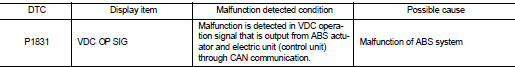
DTC DETECTION LOGIC
DTC CONFIRMATION PROCEDURE
1.DTC REPRODUCTION PROCEDURE
 With CONSULT-III
1. Start the engine and drive at 30 km/h (19 MPH) or more.
2. Perform self-diagnosis for “ALL MODE AWD/4WD”.
Is DTC “P1831” detected? YES >> Proceed to diagnosis procedure. Refer to DLN-63, "Diagnosis Procedure".
NO >> INSPECTION END
Diagnosis Procedure
1.PERFORM ABS ACTUATOR AND ELECTRIC UNIT (CONTROL UNIT) SELF-DIAGNOSIS
With CONSULT-III
Perform self-diagnosis for “ABS”.
Is any DTCs detected? YES >> Check the DTCs. Refer to BRC-142, "DTC Index".
NO >> GO TO 2.
2.ERASE SELF-DIAGNOSTIC RESULT
With CONSULT-III
1. Erase self-diagnostic results for “ALL MODE AWD/4WD”.
2. Start the engine and drive vehicle at 30 km/h (19 MPH) or more.
3. Check that ABS warning lamp turns OFF.
Does ABS warning lamp turn OFF? YES >> GO TO 3.
NO >> Refer to BRC-212, "Diagnosis Procedure".
3.CHECK TERMINALS AND HARNESS CONNECTORS
Check 4WD control module pin terminals for damage or loose connection with harness connector.
Is inspection result normal? YES >> After turning the ignition switch OFF, perform DTC confirmation procedure again. When DTC “P1831” is detected, Replace 4WD control module. Refer to DLN-91, "Removal and Installation".
NO >> Repair or replace error-detected parts.
 P1830 ABS operation signal
DTC Logic
DTC DETECTION LOGIC
DTC CONFIRMATION PROCEDURE
1.DTC REPRODUCTION PROCEDURE
With CONSULT-III
1. Start the engine and drive at 30 km/h (19 MPH) or more.
2. Perform self-diagnosis for ...
 P1832 TCS operation signal
DTC Logic
DTC DETECTION LOGIC
DTC CONFIRMATION PROCEDURE
1.DTC REPRODUCTION PROCEDURE
With CONSULT-III
1. Start the engine and drive at 30 km/h (19 MPH) or more.
2. Perform self-diagnosis for ...
Other materials:
P0697 sensor power supply
DTC Logic
DTC DETECTION LOGIC
Diagnosis Procedure
1.CHECK GROUND CONNECTION
1. Turn ignition switch OFF and wait at least 4 minutes.
2. Check ground connection E38. Refer to Ground Inspection in GI-44, "Circuit
Inspection".
Is the inspection result normal?
YES >> GO TO 2 ...
Door switch
Component Function Check
1.CHECK FUNCTION
1. Select “DOOR LOCK” of “BCM” using CONSULT-III.
2. Select “DOOR SW-DR”, “DOOR SW-AS”, “DOOR SW-RL”, “DOOR SW-RR”, “DOOR SW-BK”
in “DATA
MONITOR” mode.
3. Check that the function operates normally according to the fo ...
Light & rain sensor
Component Function Check
1.CHECK FRONT WIPER AUTO OPERATION
1. Clean rain sensor detection area of windshield fully.
2. When the front wiper switch is turned to AUTO position, front wiper operates
once regardless of a rainy
condition.
Is front wiper (AUTO) operation normally?
YES >> ...
