Nissan Juke Service and Repair Manual : Structure and operation
Transaxle : Cross-Sectional View
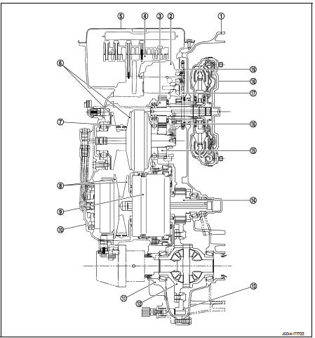
1. Converter housing
2. Oil pump
3. Counter drive gear
4. Control valve
5. Oil pan
6. Primary pulley
7. Steel belt
8. Secondary pulley
9. Planetary gear (auxiliary gearbox)
10. Side cover
11. Transaxle case
12. Differential case
13. Final gear
14. Reduction gear
15. Counter driven gear
16. Drive sprocket
17. Oil pump chain
18. Torque converter
19. Driven sprocket
Transaxle : Transaxle Mechanism
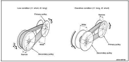
BELT & PULLEY
Mechanism
It is composed of a pair of pulleys (the groove width is changed freely in the
axial direction) and the steel belt
(the steel plates are placed continuously and the belt is guided with the
multilayer steel rings on both sides).
The groove width changes according to wrapping radius of steel belt and pulley from low status to overdrive status continuously with non-step. It is controlled with the oil pressures of primary pulley and secondary pulley.
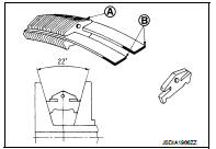
Steel belt
It is composed of multiple steel plates (A) and two steel rings (B)
stacked to a several number. The feature of this steel belt transmits
power with compression of the steel plate in contrast with transmission
of power in pulling with a rubber belt. Friction force is required
with the pulley slope to transmit power from the steel plate. The force
is generated with the following mechanism:
Oil pressure applies to the secondary pulley to nip the plate. ⇒The
plate is pushed and extended outward. ⇒The steel ring shows withstands.
⇒Pulling force is generated on the steel ring. ⇒The plate of the primary pulley is nipped between the pulley. ⇒Friction force is generated between the steel belt and the pulley.
Therefore, responsibilities are divided by the steel plate that transmits the power with compression and the steel ring that maintains necessary friction force. In this way, the tension of the steel ring is distributed on the entire surface and stress variation is limited, resulting in good durability.
Pulley
The primary pulley (input shaft side) and the secondary pulley (output shaft
side) have the shaft with slope
(fixed cone surface), movable sheave (movable cone surface that can move in the
axial direction) and oil pressure
chamber at the back of the movable sheave.
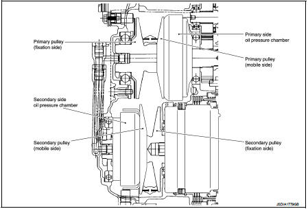
Pulley gear shifting operation • Pulley gear shifting operation The movable sheave slides on the shaft to change the groove width of the pulley. Input signals of engine load (accelerator pedal opening), engine revolution and gear ratio (vehicle speed) change the operation pressures of the primary pulley and the secondary pulley, and controls the pulley groove width. Along with change of the pulley groove width, the belt contact radius is changed. This allows continuous and stepless gear shifting from low to overdrive. “The contact radius ratio of each pulley in contact with the belt x auxiliary gearbox gear ratio” is the gear ratio.
AUXILIARY GEARBOX MECHANISM
1st, 2nd and reverse gears are changed with the planetary gear mechanism.
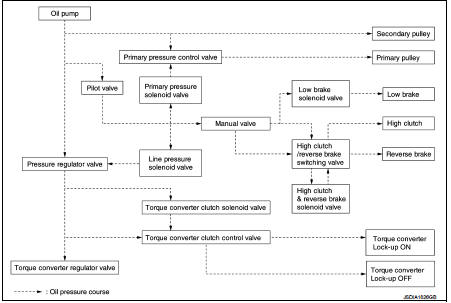
Transaxle : Oil Pressure System
Oil pressure required for operation of the transaxle transmission mechanism is generated by oil pump, oil pressure control valve, solenoid valve, etc.
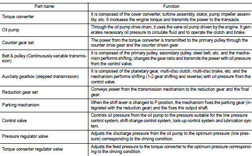
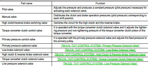
Transaxle : Component Description
Fluid cooler & fluid warmer system : System Description
CVT FLUID COOLER SCHEMATIC
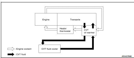
COMPONENT DESCRIPTION
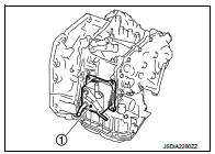
CVT Oil Warmer
• The CVT oil warmer (1) is installed on the front part of transaxle
assembly.
• When engine is started while engine and CVT are cold, engine coolant temperature rises more quickly than CVT fluid temperature.
CVT oil warmer is provided with two circuits for CVT and engine coolant respectively so that warmed engine coolant warms CVT quickly. This helps shorten CVT warming up time, improving fuel economy.
• A cooling effect is obtained when A/T fluid temperature is high.
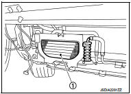
CVT Fluid Cooler
• The CVT fluid cooler (1) is installed to the radiator core support.
• The CVT fluid cooler prevents CVT fluid temperature from an abnormal increase while driving the vehicle. When flowing into the CVT fluid cooler, CVT fluid is cooled by driving blast while driving the vehicle.
Heater thermostat
• The heater thermostat is installed on the front part of transaxle assembly.
• The heater thermostat starts opening before the completion of an engine warm-up and fully opens at the completion of the engine warm-up. This allows the transaxle to be warmed up when CVT fluid temperature is lower than coolant temperature under low temperature conditions.
 Component parts
CVT control system : Component Parts Location
1. Multi display unit (MDU)*
Refer to DMS-3, "Component Parts
Location".
2. Combination meter 3. S mode indicator
(On the combination met ...
 System
CVT control system : System Diagram
CVT control system : System Description
INPUT/OUTPUT SIGNAL TABLE
*: With Nissan Dynamic Control System
SYSTEM DESCRIPTION
• CVT detects the vehicle driv ...
Other materials:
B2604 shift position
DTC Logic
DTC DETECTION LOGIC
NOTE:
• If DTC B2604 is displayed with DTC U1000, first perform the trouble diagnosis
for DTC U1000. Refer to
BCS-83, "DTC Logic".
• If DTC B2604 is displayed with DTC U1010, first perform the trouble diagnosis
for DTC U1010. Refer to
BCS-84, &qu ...
Tire pressure
Tire Pressure Monitoring System (TPMS) This vehicle is equipped with the Tire
Pressure Monitoring System (TPMS). It monitors tire pressure of all tires except
the spare. When the low tire pressure warning light is lit, and the CHECK TIRE PRES
(pressure) warning message is displayed in the vehi ...
Heater and air conditioner
WARNING
• The air conditioner cooling function operates only when the engine
is running.
• Do not leave children or adults who would normally require the support of others
alone in your vehicle. Pets should not be left alone either. On hot, sunny days,
temperatures in a closed vehi ...
