Nissan Juke Service and Repair Manual : Component parts
CVT control system : Component Parts Location
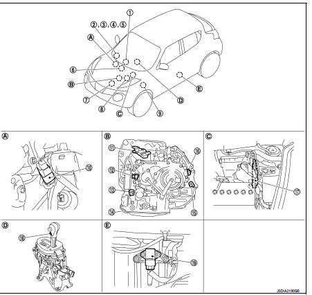
1. Multi display unit (MDU)* Refer to DMS-3, "Component Parts Location".
2. Combination meter 3. S mode indicator (On the combination meter) 4. Shift position indicator (On the combination meter) 5. Malfunction indicator lamp (MIL) (On the combination meter) 6. ABS actuator and electric unit (control unit) Refer to BRC-97, "Component Parts Location" (With ESP), BRC-9, "Component Parts Location" (Without ESP).
7. ECM Refer to EC-455, "ENGINE CONTROL SYSTEM : Component Parts Location".
8. IPDM E/R Refer to PCS-5, "Component Parts Location" (With Intelligent Key system), PCS-5, "Component Parts Location" (Without Intelligent Key system).
9. BCM
Refer to BCS-6, "BODY CONTROL
SYSTEM : Component Parts Location"
(With Intelligent Key system), BCS-96,
"BODY CONTROL SYSTEM : Component
Parts Location" (Without Intelligent
Key system)
10. Stop lamp switch
11. Transmission range switch
12. Primary speed sensor
13. CVT unit connector
14. Control valve assembly
15. Output speed sensor
16. Secondary speed sensor
17. TCM
18. S mode switch
19. G sensor
A. Brake pedal, upper
B. Transaxle assembly
C. Engine room
D. CVT shift selector assembly
E. Driver seat (LHD) or passenger seat
(RHD), under
*: With Nissan Dynamic Control System
NOTE
:
The following components are included in control valve assembly (14).
ŌĆó CVT fluid temperature sensor
ŌĆó Secondary pressure sensor
ŌĆó ROM assembly
ŌĆó Line pressure solenoid valve
ŌĆó Low brake solenoid valve
ŌĆó High clutch & reverse brake solenoid valve
ŌĆó Torque converter clutch solenoid valve
CVT control system : Component Description
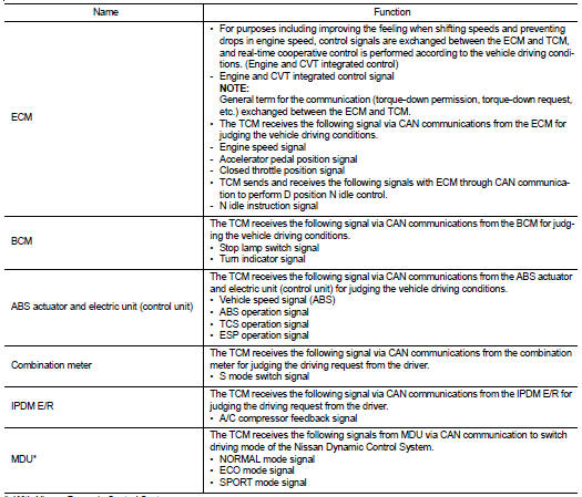
*: With Nissan Dynamic Control System
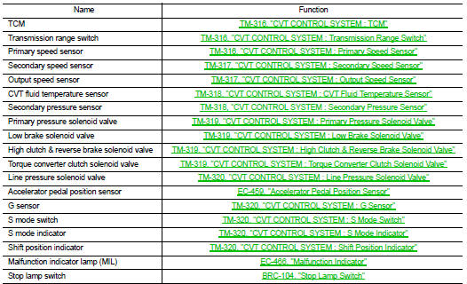
CVT control system : TCM
ŌĆó The vehicle driving status is judged based on the signals from the sensors, switches, and other control units, and the optimal transaxle control is performed.
ŌĆó For TCM control items, refer to TM-329, "CVT CONTROL SYSTEM : System Description".
System : System Description".
ŌĆó The transmission range switch is installed to upper part of transaxle case.
ŌĆó The transmission range switch detects the selector lever position.
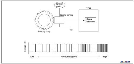
CVT control system : Primary Speed Sensor
ŌĆó The primary speed sensor is installed to side cover of transaxle.
ŌĆó The primary speed sensor detects primary pulley speed.
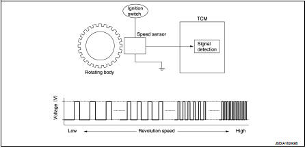
ŌĆó The primary speed sensor generates the ON-OFF pulse (short waveform) in proportion to the rotating body speed which is ŌĆ£The higher the rotating body speed is, the faster the change cycle isŌĆØ. The TCM judges the rotating speed from the changing cycle of this pulse signal.
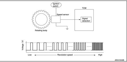
CVT control system : Secondary Speed Sensor
ŌĆó The secondary speed sensor is installed to side cover of transaxle.
ŌĆó The secondary speed sensor detects secondary pulley speed.
ŌĆó The secondary speed sensor generates the ON-OFF pulse (short waveform) in proportion to the rotating body speed which is ŌĆ£The higher the rotating body speed is, the faster the change cycle isŌĆØ. The TCM judges the rotating speed from the changing cycle of this pulse signal.
CVT control system : Output Speed Sensor
ŌĆó The output speed sensor is installed to the back side of transaxle case.
ŌĆó The output speed sensor detects final gear speed. TCM evaluates the vehicle speed from the final gear revolution.
ŌĆó The output speed sensor generates the ON-OFF pulse (short waveform) in proportion to the rotating body speed which is ŌĆ£The higher the rotating body speed is, the faster the change cycle isŌĆØ. The TCM judges the rotating speed from the changing cycle of this pulse signal.
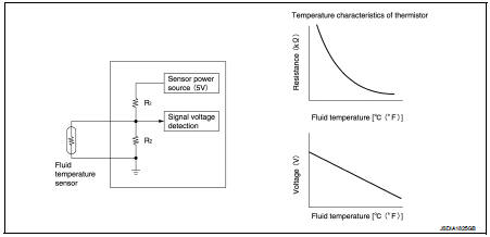
CVT control system : CVT Fluid Temperature Sensor
ŌĆó The CVT fluid temperature sensor is installed to control valve.
ŌĆó The CVT fluid temperature sensor detects CVT fluid temperature in oil pan.
ŌĆó The fluid temperature sensor uses a thermistor, and changes the signal voltage by converting changes in the CVT fluid temperature to a resistance value. TCM evaluates the CVT fluid temperature from the signal voltage value.
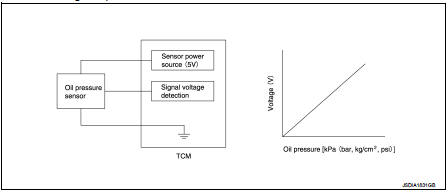
CVT control system : Secondary Pressure Sensor
ŌĆó The secondary pressure sensor is installed to control valve.
ŌĆó The secondary pressure sensor detects the pressure applied to the secondary pulley.
ŌĆó When pressure is applied to the ceramic device in the secondary pressure sensor, the ceramic device is deformed, resulting in voltage change. TCM evaluates the secondary pressure from its voltage change. Voltage is increased along with pressure increase.
CVT control system : Primary Pressure Solenoid Valve
ŌĆó The primary pressure solenoid valve is installed to control valve.
ŌĆó The primary pressure solenoid valve controls the primary pressure control valve. For information about the primary pressure control valve, refer to TM-325, "TRANSAXLE : Component Description".
ŌĆó The primary pressure solenoid valve uses the linear solenoid valve [N/H (normal high) type].
NOTE
:
ŌĆó The principle of the linear solenoid valve utilizes the fact that the force
pressing on the valve spool installed
inside the coil increases nearly in proportion to the current. This allows it to
produce a fluid pressure that is
proportional to this pressing force.
ŌĆó The N/H (normal high) produces hydraulic control when the coil is not energized.
CVT control system : Low Brake Solenoid Valv
ŌĆó The low brake solenoid valve is installed to control valve.
ŌĆó The low brake solenoid valve adjusts the tightening pressure of the low brake.
ŌĆó The low brake solenoid valve uses the linear solenoid valve [N/L (normal low) type].
NOTE
:
ŌĆó The principle of the linear solenoid valve utilizes the fact that the force
pressing on the valve spool installed
inside the coil increases nearly in proportion to the current. This allows it to
produce a fluid pressure that is
proportional to this pressing force.
ŌĆó The N/L (normal low) type does not produce hydraulic control when the coil is not energized.
CVT control system : High Clutch & Reverse Brake Solenoid Valve
ŌĆó The high clutch & reverse brake solenoid valve is installed to control valve.
ŌĆó The high clutch & reverse brake solenoid valve adjusts the tightening pressure of the high clutch and reverse brake.
ŌĆó The high clutch & reverse brake solenoid valve uses the linear solenoid valve [N/H (normal high) type].
NOTE
:
ŌĆó The principle of the linear solenoid valve utilizes the fact that the force
pressing on the valve spool installed
inside the coil increases nearly in proportion to the current. This allows it to
produce a fluid pressure that is
proportional to this pressing force.
ŌĆó The N/H (normal high) produces hydraulic control when the coil is not energized.
CVT control system : Torque Converter Clutch Solenoid Valve
ŌĆó The torque converter clutch solenoid valve is installed to control valve.
ŌĆó The torque converter clutch solenoid valve controls the torque converter clutch control valve. For information about the torque converter clutch control valve, refer to TM-325, "TRANSAXLE : Component Description".
ŌĆó The torque converter clutch solenoid valve utilizes a linear solenoid valve [N/L (normal low) type].
NOTE
:
ŌĆó The principle of the linear solenoid valve utilizes the fact that the force
pressing on the valve spool installed
inside the coil increases nearly in proportion to the current. This allows it to
produce a fluid pressure that is
proportional to this pressing force.
ŌĆó The N/L (normal low) type does not produce hydraulic control when the coil is not energized.
CVT control system : Line Pressure Solenoid Valv
ŌĆó The line pressure solenoid valve is installed to control valve.
ŌĆó The line pressure solenoid valve controls the pressure regulator valve. For information about the pressure regulator valve, refer to TM-325, "TRANSAXLE : Component Description".
ŌĆó The line pressure solenoid valve uses the linear solenoid valve [N/H (normal high) type].
NOTE
:
ŌĆó The principle of the linear solenoid valve utilizes the fact that the force
pressing on the valve spool installed
inside the coil increases nearly in proportion to the current. This allows it to
produce a fluid pressure that is
proportional to this pressing force.
ŌĆó The N/H (normal high) produces hydraulic control when the coil is not energized.
CVT control system : G Sensor
ŌĆó G sensor is installed to floor under instrument lower cover.
ŌĆó G sensor detects front/rear G and inclination applied to the vehicle.
ŌĆó G sensor converts front/rear G and inclination applied to the vehicle to voltage signal. TCM evaluates front/ rear G and inclination angle of the vehicle from the voltage signal.
CVT control system : S Mode Switch
ŌĆó The S mode switch is installed to the selector lever knob.
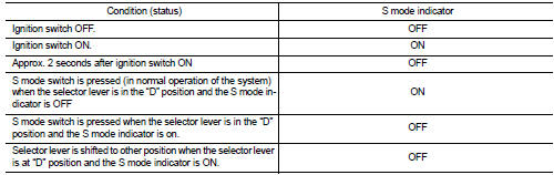
ŌĆó When the S mode indicator on the combination meter is OFF and the S mode switch is pressed, the S mode is active and the S mode indicator is ON.
ŌĆó When the S mode indicator on the combination meter is ON and the S mode switch is pressed, the S mode is cancelled and the S mode indicator is OFF.
CVT control system : S Mode Indicator
ŌĆó S mode indicator is positioned on the combination meter.
ŌĆó The S mode indicator is ON when set to the S mode.
ŌĆó S mode indicator turns on for a certain period of time when the ignition switch turns ON, and then turns off.
CVT control system : Shift Position Indica
TCM transmits shift position signal to combination meter via CAN communication. The actual shift position is displayed on combination meter according to the signal.
A/T shift lock system : Component Parts Location
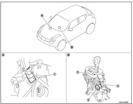
1. Stop lamp switch
2. Shift lock release button
3. Shift lock solenoid
4. Park position switch
A: Brake pedal, upper B: CVT shift selector assembly
A/T shift lock system : Component Desc
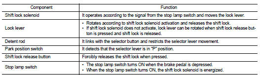

 Structure and operation
Transaxle : Cross-Sectional View
1. Converter housing
2. Oil pump
3. Counter drive gear
4. Control valve
5. Oil pan
6. Primary pulley
7. Steel belt
8. Secondary pulley
9. Planetary ge ...
Other materials:
Condenser
Exploded View
Refer toINT-34, "Exploded View"
Removal and Installation
REMOVAL
1. Remove the back door lower finisher.
Refer to INT-35, "BACK DOOR LOWER FINISHER : Removal and Installation"
2. Remove bolt (A), and then remove condenser (1) from the vehicle
body.
INSTA ...
Vehicle speed sensing auto lock operation does not operate
Diagnosis Procedure
1.CHECK ŌĆ£AUTOMATIC LOCK/UNLOCK SELECTŌĆØ SETTING IN ŌĆ£WORK SUPPORTŌĆØ
1. Select ŌĆ£DOOR LOCKŌĆØ of ŌĆ£BCMŌĆØ using CONSULT-III.
2. Select ŌĆ£AUTOMATIC LOCK/UNLOCK SELECTŌĆØ in ŌĆ£WORK SUPPORTŌĆØ mode.
3. Check ŌĆ£AUTOMATIC LOCK/UNLOCK SELECTŌĆØ in ŌĆ£WORK SUPPORTŌĆØ.
Re ...
P0089 fuel pump
DTC Logic
DTC DETECTION LOGIC
NOTE:
ŌĆó Conditions for applying the diagnostic procedure to the stored DTCs:
The DTC becomes present during the first 30 seconds after the engine starts.
ŌĆó In low ambient temperature conditions, diagnostic cannot make difference
between a normal long engine ...
