Nissan Juke Service and Repair Manual : B1147 curtain air bag module RH
DTC Logic
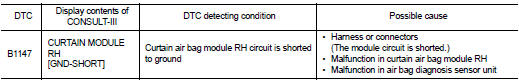
DTC DETECTION LOGIC
DTC CONFIRMATION PROCEDURE
1.CHECK SELF-DIAG RESULT
 With CONSULT-III
1. Turn ignition switch ON.
2. Perform “Self Diagnostic Result” mode of “AIR BAG” using CONSULT-III.
 Without CONSULT-III
1. Turn ignition switch ON.
2. Check the air bag warning lamp status. Refer to SRC-12, "On Board Diagnosis Function".
NOTE
:
SRS does not enter the diagnosis mode if no malfunction is detected in the user
mode.
Is malfunctioning part detected? YES >> Refer to SRC-116, "Diagnosis Procedure".
NO >> INSPECTION END
Diagnosis Procedure
WARNING:
• Before servicing, turn ignition switch OFF, disconnect battery negative
terminal, and wait at least 3
minutes or more. (To discharge backup capacitor.)
• Never use unspecified tester or other measuring device.
1.CHECK HARNESS CONNECTOR
Check the harness connector.
Is the inspection result normal? YES >> GO TO 2.
NO >> Replace harness connector.
2.CHECK WIRING HARNESS
Check the wiring harness externals.
Is the inspection result normal? YES >> GO TO 3.
NO >> Replace wiring harness.
3.REPLACE AIR BAG DIAGNOSIS SENSOR UNIT
1. Replace air bag diagnosis sensor unit. Refer to SR-30, "Removal and Installation".
2. Perform DTC confirmation procedure. Refer to SRC-116, "DTC Logic".
Is DTC detected? YES >> GO TO 4.
NO >> INSPECTION END
4.REPLACE CURTAIN AIR BAG MODULE
1. Replace curtain air bag module RH. Refer to SR-24, "Removal and Installation".
2. Perform DTC confirmation procedure. Refer to SRC-116, "DTC Logic".
Is DTC detected?
YES >> GO TO 1.
NO >> INSPECTION END
 B1146 curtain air bag module RH
DTC Logic
DTC DETECTION LOGIC
DTC CONFIRMATION PROCEDURE
1.CHECK SELF-DIAG RESULT
With CONSULT-III
1. Turn ignition switch ON.
2. Perform “Self Diagnostic Result” mode of “AIR BAG” usi ...
 B1148 curtain air bag module
DTC Logic
DTC DETECTION LOGIC
DTC CONFIRMATION PROCEDURE
1.CHECK SELF-DIAG RESULT
With CONSULT-III
1. Turn ignition switch ON.
2. Perform “Self Diagnostic Result” mode of “AIR BAG” usi ...
Other materials:
Front seat belt
Exploded View
1. Adjuster cover
2. Anchor bolt
3. Shoulder anchor
4. Spacer
5. Retaining washer
6. Seat belt adjuster
7. Seat belt pre-tensioner retractor
(Passenger side)
8. Outer anchor
9. Seat belt pre-tensioner retractor
(Driver side)
10. Seat belt buckle
11. Wave washer
&n ...
Hazard function
Component Function Check
1.CHECK FUNCTION
1. Select “INTELLIGENT KEY” of “BCM” using CONSULT-III.
2. Select “FLASHER” in “ACTIVE TEST” mode.
3. Check that the function operates normally according to the following
conditions.
Is the inspection result normal?
YES >> Haz ...
Configuration (bcm)
Description
Vehicle specification needs to be written with CONSULT-III because it is not
written after replacing BCM.
Configuration has three functions as follows.
NOTE:
Manual setting item: Items which need selection by vehicle specifications
Automatic setting item: Items which are written ...
