Nissan Juke Service and Repair Manual : Wiring diagram
POWER SOCKET
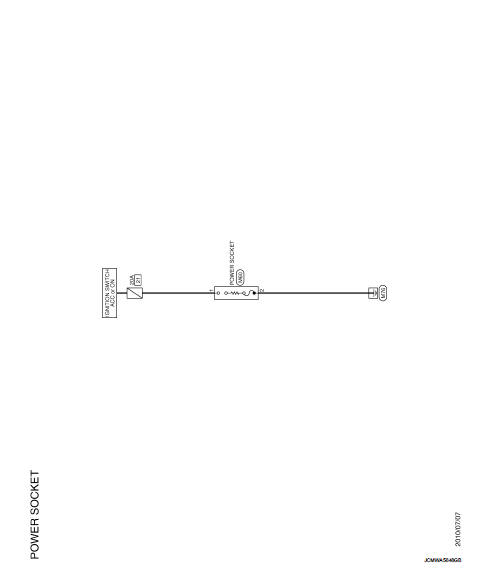
Wiring Diagram
For connector terminal arrangements, harness layouts, and alphabets in a
 (option abbreviation; if not
described in wiring diagram), refer to GI-12, "Connector Information/Explanation
of Option Abbreviation".
 Precaution
Precaution for Supplemental Restraint System (SRS) "AIR BAG" and "SEAT
BELT
PRE-TENSIONER"
The Supplemental Restraint System such as “AIR BAG” and “SEAT BELT
PRE-TENSIO ...
 Removal and installation
POWER SOCKET
Exploded View
1 : Inner socket
2 : Ring
Removal and Installation
REMOVAL
1. Remove cluster tray. Refer to IP-13, "Removal and Installation".
2. Pull out inner socket (1 ...
Other materials:
Precaution
REPAIRING HIGH STRENGTH STEEL
High Strength Steel (HSS)
High strength steel is used for body panels in order to reduce vehicle
weight.
Accordingly, precautions in repairing automotive bodies made of high strength
steel are described below:
FOR 2WD MODELS
FOR 4WD MODELS
Read the follo ...
Rear door glass
Exploded View
1. Rear door panel
2. Sealing screen
3. Lower sash (front)
4. Rear door regulator assembly
5. Power window motor
6. Rear door glass
7. Lower sash (rear)
8. Rear door glass run
Removal and Installation
REMOVAL
1. Fully open rear door glass.
2. Remove rear door finishe ...
Rear-facing child restraint installation using LATCH
Before proceeding with the installation of any child safety seat, please ensure you have thoroughly reviewed all Warnings and Cautions detailed in the "Child safety" and "Child restraints" sections of your Owner's Manual to ensure full compliance with safety standards.
Important weight restrict ...
