Nissan Juke Service and Repair Manual : Removal and installation
POWER SOCKET
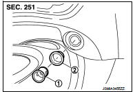
Exploded View
1 : Inner socket
2 : Ring
Removal and Installation
REMOVAL
1. Remove cluster tray. Refer to IP-13, "Removal and Installation".
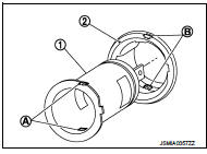
2. Pull out inner socket (1) by pushing the pawl (B) of the ring (2) from the inner socket hole (square) (A).
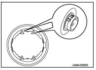
3. Press the ring pawl from the back of the cluster tray to remove the ring.
 : Pawl
INSTALLATION
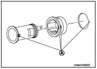
Note the following, and install in the reverse order of removal.
Align the cut outs of inner socket, ring and cluster tray.
A : Cut out
 Wiring diagram
POWER SOCKET
Wiring Diagram
For connector terminal arrangements, harness layouts, and alphabets in a
(option abbreviation; if not
described in wiring diagram), refer to GI-12, "Connector Inf ...

Other materials:
Intelligent key low battery warning does not operate
Diagnosis Procedure
1.CHECK DTC WITH BCM AND COMBINATION METER
Check that DTC is not detected with BCM and combination meter.
Is the inspection result normal?
YES >> GO TO 2.
NO-1 >> Refer to BCS-67, "DTC Index". (BCM)
NO-2 >> Refer to MWI-36, "DTC Index&qu ...
Li-ion battery life
Like all energy storage systems, the Li-ion battery in your Nissan Leaf will naturally experience a gradual decrease in its total capacity over time and with consistent usage. This manifests as a subtle reduction in your maximum driving range compared to when the vehicle was brand new. Please unders ...
System
Interior room lamp control system
INTERIOR ROOM LAMP CONTROL SYSTEM : System Diagram
INTERIOR ROOM LAMP CONTROL SYSTEM : System Description
OUTLINE
• Interior room lamps* are controlled by interior room lamp timer control
function of BCM.
*: Map lamp (when map lamp switch is in DOOR posit ...
