Nissan Juke Service and Repair Manual : Sill cover
Exploded View
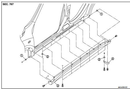
1. Screw grommet
2. Screw grommet
3. Sill cover
4. Wind defle
Removal and Installation
REMOVAL
1. Remove sill cover front end fixing screw (A).
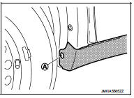
2. Remove sill cover rear end fixing screw (A).
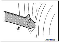
3. Remove sill cover lower side fixing screws.
4. Fully open front door and rear door.
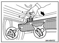
5. Remove clips from sill cover back side with a remover tool (A).
 : Clip
CAUTION:
Apply protective tape (B) on the body to protect the painted
surface from damage.
6. Remove sill cover form body side.
INSTALLATION
Note the following item, and then install in the reverse order of removal.
CAUTION:
When installing sill cover, check that clips are securely fitted in body panel
holes, and then press clips
in.
 Fender protector
Exploded View
1. Hoodledge insurator
2. Fender protector
3. U nut
4. Air guide
5. Screw grommet
A. To hoodledge panel
: Vehicle front
Removal and Installation
REMOVAL
1. Remove front fi ...
 Floor side fairing
Exploded View
1. Push spring nut
2. Floor under cover RH
3. Floor under cover LH
Removal and Installation
REMOVAL
FLOOR UNDER COVER
Remove floor under cover mounting nut and push spring nut ...
Other materials:
Fuel filler lid opener
Exploded View
1. Fuel filler lid opener cable
2. Cable protector
3. Fuel filler lid lock assembly
4. Fuel filler lid assembly
5. Spring
6. Bumper rubber
: Clip
: Do not reuse
Fuel filler lid
FUEL FILLER LID : Removal and Installation
REMOVAL
1. Fully open fuel filler lid.
2. Remove ...
Intelligent Key system (if so equipped)
WARNING
• Radio waves could adversely affect electric medical equipment. Those who
use a pacemaker should contact the electric medical equipment manufacturer for the
possible influences before use.
• The Intelligent Key transmits radio waves when the buttons are pushed. The FAA
advises t ...
Heater and air conditioner
WARNING
• The air conditioner cooling function operates only when the engine
is running.
• Do not leave children or adults who would normally require the support of others
alone in your vehicle. Pets should not be left alone either. On hot, sunny days,
temperatures in a closed vehi ...
