Nissan Juke Service and Repair Manual : Control cable
Exploded View
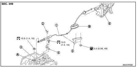
1. Control cable
2. Lock plate
3. Transaxle assembly
4. Bracket A
5. Bracket B
6. CVT shift selector assembly
A: Manual lever
B: Grommet
 : N·m (kg-m, ft-lb)
 : N·m (kg-m, in-lb)
Removal and Installation
INSTALLATION
CAUTION:
Always apply the parking brake before performing removal and installation.
1. Remove the battery. Refer to PG-124, "Removal and Installation".
2. Remove the control cable from the CVT shift selector assembly. Refer to TM-481, "Removal and Installation".
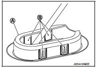
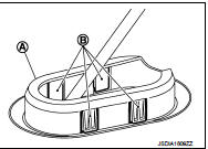
3. Disengage the pawls (B) of the grommet (A), and pull downwards to remove.
4. Remove the control cable installation nut from the manual lever.
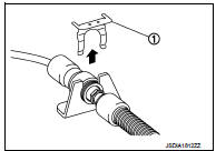
5. Remove the lock plate (1).
6. Remove sub muffler from the mounting rubber and lower the sub muffler downward. Refer to EX-12, "Exploded View".
7. Lift up the heat plate.
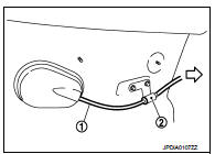
8. Remove the control cable (1) from the bracket (2).
 :Vehicle front
9. Remove the control cable from the vehicle.
10. Remove bracket.
INSTALLATION
Note the following, and install in the reverse order of removal.
• From below the vehicle, press the grommet (A) into place until the pawls (B) make a click sound.
CAUTION:
• Place the grommet on the floor, then fasten it in place from
below the vehicle.
• Check that pulling down on the grommet does not disconnect it.
• Pay attention to the following when connecting the control cable to the CVT shift selector.
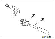
1. When connecting the control cable (1) to the CVT shift selector assembly (2), face the grooved surface of the rib (A) up and insert the control cable until it stops.
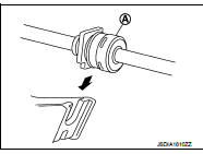
2. Install the socket (A) onto the CVT shift selector.
CAUTION:
• Place the socket onto the CVT shift lever, then fasten it in
place from above.
• Check that the pulling on the socket does not disconnect it.
Inspection
INSPECTION AFTER INSTALLATION
Check the CVT position. If a malfunction is found, adjust the CVT position. Refer to TM-383, "Inspection and Adjustment".
 CVT shift selector
Exploded View
1. Selector lever knob
2. Lock pin
3. Knob cover
4 Position indication panel
5. CVT shift selector assembly
6. CVT shift selector harness assembly
7. Detent switch*
8. Shi ...
 Key interlock cable
Exploded View
1. CVT shift selector assembly
2. Key interlock cable
A: Key cylinder
B: Clip
C: Clip
Removal and Installation
REMOVAL
CAUTION:
Always apply the parking brake before perfor ...
Other materials:
B1120 satellite sensor LH
DTC Logic
DTC DETECTION LOGIC
DTC CONFIRMATION PROCEDURE
1.CHECK SELF-DIAG RESULT
With CONSULT-III
1. Turn ignition switch ON.
2. Perform “Self Diagnostic Result” mode of “AIR BAG” using CONSULT-III.
Without CONSULT-III
1. Turn ignition switch ON.
2. Check the air bag warning la ...
Draining
WARNING:
• Never remove radiator cap when engine is hot. Serious burns may occur from
high-pressure engine
coolant escaping from radiator.
• Wrap a thick cloth around the radiator cap. Slowly turn it a quarter of a turn
to release built-up pressure.
Then turn it all the way.
1. Remove ...
Unit removal and installation
Transaxle assembly
Exploded View
1. Transaxle assembly
: Refer to "INSTALLATION" in
TM-30, "Removal and Installation" for the locations and tightening torque.
Removal and Installation
CAUTION:
Never reuse CSC (Concentric Slave Cylinder). Because CSC slides back to the
...
