Nissan Juke Service and Repair Manual : Key interlock cable
Exploded View
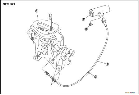
1. CVT shift selector assembly 2. Key interlock cable
A: Key cylinder
B: Clip
C: Clip
Removal and Installation
REMOVAL
CAUTION:
Always apply the parking brake before performing removal and installation.
1. Shift the selector lever to the “P” position.
2. Remove the selector lever knob. Refer to TM-482, "Disassembly and Assembly".
3. Remove the center console. Refer to IP-23, "Removal and Installation".
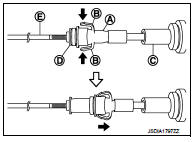
4. Press the pawls (B) of the key interlock cable slider (A) while sliding it in the direction of the casing cap (C), and separate the adjusting holder (D) and slider.
E :Key interlock rod
5. Remove the key interlock cable from the CVT shift selector.
6. Remove the steering column lower cover and driver instrument lower panel. Refer to IP-13, "Removal and Installation".
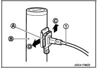
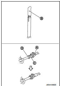
7. Lift clip (A) in the direction of the arrow (
 C) and remove in the
direction of the arrow (  D).
D).
1 :Key interlock cable B :Key cylinder
8. Disconnect the key interlock cable from the key cylinder.
9. Disengage the clip and disconnect the key interlock cable from the vehicle.
INSTALLATION
• Install the adjusting holder (A) onto the key interlock rod (B), then install the casing cap (C) onto the CVT shift selector cable bracket (D).
CAUTION:
• When installing the key interlock cable, never bend or twist
the cable forcefully.
• After connecting the key interlock cable to the CVT shift selector cable bracket, be sure to check that the casing cap is completely fastened to the cable bracket. If the casing cap is easily displaced, replace the key interlock cable.
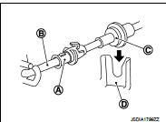
• While pressing the detent rod (B) down, slide the key interlock cable slider (A) toward the key interlock rod (D) side, and install the adjusting holder (C) and key interlock rod.
CAUTION:
• Never squeeze the pawls on the key interlock cable slider
when holding the slider.
• Never apply force in a perpendicular direction to the key interlock rod when sliding the slider.
Inspection
INSPECTION AFTER INSTALLATION
• Check the CVT position. If a malfunction is found, adjust the CVT position. Refer to TM-383, "Inspection and Adjustment".
• The key can be removed only when the selector lever is in the “P” position.
• It must not be possible to turn the ignition switch to LOCK when the selector lever is not in the “P” position.
 Control cable
Exploded View
1. Control cable
2. Lock plate
3. Transaxle assembly
4. Bracket A
5. Bracket B
6. CVT shift selector assembly
A: Manual lever
B: Grommet
: N·m (kg-m, ft-lb)
: N·m (kg- ...
 TCM
TCM
Exploded View
1. Bracket
2. TCM
:Vehicle front
: N·m (kg-m, in-lb)
Removal and Installation
CAUTION:
When replacing TCM, note the “CVTF DETERIORATION DATE” value displayed on
CONSULT- ...
Other materials:
Power supply and ground circuit
Diagnosis Procedure
1.CHECK ABS ACTUATOR AND ELECTRIC UNIT (CONTROL UNIT) IGNITION POWER
SUPPLY
1. Turn the ignition switch OFF.
2. Disconnect ABS actuator and electric unit (control unit) harness connector.
3. Check voltage between ABS actuator and electric unit (control unit) harness
conne ...
B27A2, B27A3, B27A4, B27A5 air mix door motor
DTC Logic
DTC DETECTION LOGIC
NOTE:
• If DTC is displayed along with DTC U1000, first perform the trouble diagnosis
for DTC U1000. Refer to HAC-
51, "DTC Logic".
• If DTC is displayed along with DTC U1010, first perform the trouble diagnosis
for DTC U1010. HAC-52,
"DTC L ...
Seat belt buckle switch signal circuit (driver side)
Component Function Check
1.CHECK COMBINATION METER INPUT SIGNAL
Select the “Data Monitor” for the “METER/M&A” and check the “BUCKLE SW”
monitor value.
BUCKLE SW
When driver seat belt is fastened : Off
When driver seat belt is unfastened : On
>> INSPECTION END
Diagnosis ...
