
Nissan Juke Service and Repair Manual : P2101 electric throttle control function
DTC Logic
DTC DETECTION LOGIC
NOTE
:
• If DTC P2101 is displayed with DTC P2100, first perform the trouble diagnosis
for DTC P2100. Refer
to EC-376, "DTC Logic".
• If DTC P2101 is displayed with DTC P2119, first perform the trouble diagnosis for DTC P2119. Refer to EC-383, "DTC Logic".

DTC CONFIRMATION PROCEDURE
1.PRECONDITIONING
If DTC Confirmation Procedure has been previously conducted, always perform the following procedure before conducting the next test.
1. Turn ignition switch OFF and wait at least 10 seconds.
2. Turn ignition switch ON.
3. Turn ignition switch OFF and wait at least 10 seconds.
TESTING CONDITION:
Before performing the following procedure, confirm that battery voltage is more
than 11 V when
engine is running.
>> GO TO 2.
2.PERFORM DTC CONFIRMATION PROCEDURE
1. Turn ignition switch ON and wait at least 2 seconds.
2. Start engine and let it idle for 5 seconds.
3. Check DTC.
Is DTC detected? YES >> Proceed to EC-378, "Diagnosis Procedure".
NO >> INSPECTION END
Diagnosis Procedure
1.CHECK THROTTLE CONTROL MOTOR RELAY INPUT SIGNAL
Check the voltage between ECM harness connector terminals as per the following conditions.
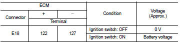
Is the inspection result normal? YES >> GO TO 4.
NO >> GO TO 2.
2.CHECK THROTTLE CONTROL MOTOR RELAY INPUT SIGNAL CIRCUIT
1. Turn ignition switch OFF.
2. Disconnect ECM harness connector.
3. Disconnect IPDM E/R harness connector.
4. Check the continuity between ECM harness connector and IPDM E/R harness connector.
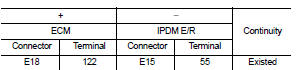
5. Also check harness for short to ground and to power.
Is the inspection result normal? YES >> GO TO 3.
NO >> Repair or replace error-detected parts.
3.CHECK THROTTLE CONTROL MOTOR RELAY POWER SUPPLY CIRCUIT
1. Check the continuity between ECM harness connector and IPDM E/R harness connector.
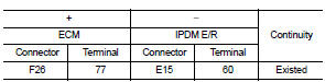
2. Also check harness for short to ground.
Is the inspection result normal? YES >> Perform the trouble diagnosis for power supply circuit.
NO >> Repair or replace error-detected parts.
4.CHECK THROTTLE CONTROL MOTOR OUTPUT SIGNAL CIRCUIT
1. Turn ignition switch OFF.
2. Disconnect electric throttle control actuator harness connector.
3. Disconnect ECM harness connector.
4. Check the continuity between electric throttle control actuator harness connector and ECM harness connector.
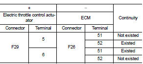
5. Also check harness for short to ground and to power.
Is the inspection result normal? YES >> GO TO 5.
NO >> Repair or replace error-detected parts.
5.CHECK ELECTRIC THROTTLE CONTROL ACTUATOR VISUALLY
1. Remove the intake air duct. Refer to EM-26, "Exploded View".5. Also check harness for short to ground and to power.
Is the inspection result normal? YES >> GO TO 5.
NO >> Repair or replace error-detected parts.
5.CHECK ELECTRIC THROTTLE CONTROL ACTUATOR VISUALLY 1. Remove the intake air duct. Refer to EM-26, "Exploded View".
2. Check if foreign matter is caught between the throttle valve and the housing.
Is the inspection result normal? YES >> GO TO 6.
NO >> Remove the foreign matter and clean the electric throttle control actuator inside, then perform throttle valve closed position learning. Refer to EC-135, "Work Procedure".
2. Check if foreign matter is caught between the throttle valve and the housing.
Is the inspection result normal? YES >> GO TO 6.
NO >> Remove the foreign matter and clean the electric throttle control actuator inside, then perform throttle valve closed position learning. Refer to EC-135, "Work Procedure".
6.CHECK THROTTLE CONTROL MOTOR
Check the throttle control motor. Refer to EC-380, "Component Inspection".
Is the inspection result normal? YES >> Check intermittent incident. Refer to GI-42, "Intermittent Incident".
NO >> Replace electric throttle control actuator. Refer to EM-28, "Exploded View".
Component Inspection
1.CHECK THROTTLE CONTROL MOTOR
1. Turn ignition switch OFF.
2. Disconnect electric throttle control actuator harness connector.
3. Check the resistance between electric throttle control actuator terminals as per the following.
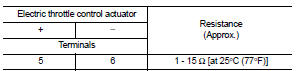
Is the inspection result normal? YES >> INSPECTION END
NO >> Replace electric throttle control actuator. Refer to EM-28, "Exploded View".
 P2100, P2103 throttle control motor relay
DTC Logic
DTC CONFIRMATION PROCEDURE
1.PRECONDITIONING
If DTC Confirmation Procedure has been previously conducted, always perform
the following procedure
before conducting the next test.
1. ...
 P2118 throttle control motor
DTC Logic
DTC DETECTION LOGIC
DTC CONFIRMATION PROCEDURE
1.PRECONDITIONING
If DTC Confirmation Procedure has been previously conducted, always perform
the following procedure
before conductin ...
Other materials:
Engine emits blue smoke
Description
CHART 19: ENGINE EMITS BLUE SMOKE
Diagnosis Procedure
1.CHECK ENGINE OIL
Check the grade of engine oil. Refer to LU-33, "Inspection".
Is the inspection result normal?
YES >> GO TO 2.
NO >> Replace engine oil. Refer to LU-34, "Refilling".
2.CH ...
B1185 lap Pre-tensioner LH
DTC Logic
DTC CONFIRMATION PROCEDURE
1.CHECK SELF-DIAGNOSTIC RESULT
With CONSULT-III
1. Turn ignition switch ON.
2. Perform “Self Diagnostic Result� mode of “AIR BAG� using CONSULT-III.
Without CONSULT-III
1. Turn ignition switch ON.
2. Check the air bag warning lamp status. Refe ...
P0335 CKP sensor (POS)
DTC Logic
DTC DETECTION LOGIC
NOTE:
If DTC P0340 is displayed with DTC P0643, first perform the trouble diagnosis
for DTC P0643.
Refer to EC-307, "DTC Logic".
DTC CONFIRMATION PROCEDURE
1.PRECONDITIONING
If DTC Confirmation Procedure has been previously conducted, always perfo ...
