Nissan Juke Service and Repair Manual : P2100, P2103 throttle control motor relay
DTC Logic
DTC CONFIRMATION PROCEDURE
1.PRECONDITIONING
If DTC Confirmation Procedure has been previously conducted, always perform the following procedure before conducting the next test.
1. Turn ignition switch OFF and wait at least 10 seconds.
2. Turn ignition switch ON.
3. Turn ignition switch OFF and wait at least 10 seconds.
TESTING CONDITION:
Before performing the following procedure, confirm that battery voltage is more
than 8 V
.
Witch DTC is detected? P2100 >> GO TO 2.
P2103 >> GO TO 3.
2.PERFORM DTC CONFIRMATION PROCEDURE FOR DTC P2100
1. Turn ignition switch ON and wait at least 2 seconds.
2. Start engine and let it idle for 5 seconds.
3. Check DTC.
Is DTC detected? YES >> Proceed to EC-376, "Diagnosis Procedure".
NO >> INSPECTION END
3.PERFORM DTC CONFIRMATION PROCEDURE FOR DTC P2103
1. Turn ignition switch ON and wait at least 1 second.
2. Check DTC.
Is DTC detected? YES >> Proceed to EC-376, "Diagnosis Procedure".
NO >> INSPECTION END
Diagnosis Procedure
1.CHECK THROTTLE CONTROL MOTOR RELAY POWER SUPPLY
1. Turn ignition switch OFF.
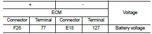
2. Check the voltage between ECM harness connector and ground.
Is the inspection result normal? YES >> GO TO 3.
NO >> GO TO 2.
2.CHECK THROTTLE CONTROL MOTOR RELAY POWER SUPPLY CIRCUIT
1. Disconnect ECM harness connector.
2. Disconnect IPDM E/R harness connector.
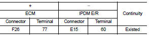
3. Check the continuity between ECM harness connector and IPDM E/R harness connector.
4. Also check harness for short to ground.
Is the inspection result normal? YES >> Perform the trouble diagnosis for power supply circuit.
NO >> Repair or replace error-detected parts.
3.CHECK THROTTLE CONTROL MOTOR RELAY INPUT SIGNAL
Check the voltage between ECM harness connector and ground as per the following conditions.

Is the inspection result normal? YES >> Check intermittent incident. Refer to GI-42, "Intermittent Incident".
NO >> GO TO 4.
4.CHECK THROTTLE CONTROL MOTOR RELAY INPUT SIGNAL CIRCUIT
1. Turn ignition switch OFF.
2. Disconnect ECM harness connector.
3. Disconnect IPDM E/R harness connector.
4. Check the continuity between ECM harness connector and IPDM E/R harness connector.

5. Also check harness for short to ground and to power.
Is the inspection result normal? YES >> Check intermittent incident. Refer to GI-42, "Intermittent Incident".
NO >> Repair or replace error-detected parts.
 P1805 brake switch
DTC Logic
DTC DETECTION LOGIC
DTC CONFIRMATION PROCEDURE
1.PERFORM DTC CONFIRMATION PROCEDURE
1. Turn ignition switch ON.
2. Fully depress the brake pedal for at least 5 seconds.
3. Erase the ...
 P2101 electric throttle control function
DTC Logic
DTC DETECTION LOGIC
NOTE:
• If DTC P2101 is displayed with DTC P2100, first perform the trouble diagnosis
for DTC P2100. Refer
to EC-376, "DTC Logic".
• If DTC P2101 is ...
Other materials:
System
POWER DISTRIBUTION SYSTEM
POWER DISTRIBUTION SYSTEM : System Description
SYSTEM DESCRIPTION
• PDS (POWER DISTRIBUTION SYSTEM) is the system that BCM controls with the
operation of the pushbutton
ignition switch and performs the power distribution to each power circuit. This
system is used ...
Brake pedal
Exploded View
WITHOUT ESP
1. Clevis pin
2. Brake pedal assembly
3. Brake pedal pad
4. Stop lamp switch
5. Clip
6. Snap pin
: Apply multi-purpose grease.
: N·m (kg-m, ft-lb)
WITH ESP
1. Clevis pin
2. Brake pedal assembly
3. Brake pedal pad
4. Brake switch/brake pedal position ...
Meters and Gauges
Vehicle information display:
Digital clock
Outside air temperature reading
Li-ion battery available charge gauge
Estimated driving range
Odometer and twin trip odometer readings
Charging tim ...
