Nissan Juke Service and Repair Manual : P1805 brake switch
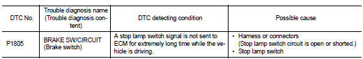
DTC Logic
DTC DETECTION LOGIC
DTC CONFIRMATION PROCEDURE
1.PERFORM DTC CONFIRMATION PROCEDURE
1. Turn ignition switch ON.
2. Fully depress the brake pedal for at least 5 seconds.
3. Erase the DTC.
4. Check 1st trip DTC.
Is 1st trip DTC detected? YES >> Proceed to EC-374, "Diagnosis Procedure".
NO >> INSPECTION END
Diagnosis Procedure
1.CHECK STOP LAMP SWITCH POWER SUPPLY CIRCUIT
1. Turn ignition switch OFF.
2. Disconnect stop lamp switch harness connector.
3. Check the voltage between stop lamp switch harness connector and ground.
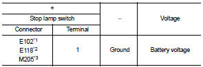
*1: CVT models
*2: LHD with M/T models
*3: RHD with M/T models
Is the inspection result normal? YES >> GO TO 2.
NO >> Perform the trouble diagnosis for power supply circuit.
2.CHECK STOP LAMP SWITCH INPUT SIGNAL CIRCUIT
1. Disconnect ECM harness connector.
2. Check the continuity between stop lamp switch harness connector and ECM harness connec
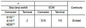
*1: CVT models
*2: LHD with M/T models
*3: RHD with M/T models
3. Also check harness for short to ground and to power.
Is the inspection result normal? YES >> GO TO 3.
NO >> Repair or replace error-detected parts.
3.CHECK STOP LAMP SWITCH
Check the stop lamp switch. Refer to EC-375, "Component Inspection (Stop Lamp Switch)".
Is the inspection result normal? YES >> Check intermittent incident. Refer to GI-42, "Intermittent Incident".
NO >> Replace stop lamp switch. Refer to BR-20, "Exploded View" (LHD) or BR-88, "Exploded View" (RHD).
Component Inspection (Stop Lamp Switch)
1.CHECK STOP LAMP SWITCH-I
1. Turn ignition switch OFF.
2. Disconnect stop lamp switch harness connector.
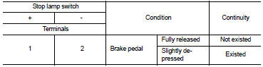
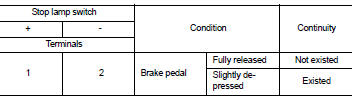
3. Check the continuity between stop lamp switch terminals as per the following conditions.
Is the inspection result normal? YES >> INSPECTION END
NO >> GO TO 2.
2.CHECK STOP LAMP SWITCH-II
1. Adjust stop lamp switch installation. Refer to BR-9, "Inspection and Adjustment" (LHD) or BR-77, "Inspection and Adjustment" (RHD).
2. Check the continuity between stop lamp switch terminals as per the following conditions.
Is the inspection result normal? YES >> INSPECTION END
NO >> Replace stop lamp switch. Refer to BR-20, "Exploded View" (LHD) or BR-88, "Exploded View" (RHD).
 P1652 starter motor system COMM
Description
ECM controls ON/OFF state of the starter relay, according to the engine and
vehicle condition. Models with no
Intelligent Key System transmit a control signal directly to IPDM E/R. On ...
 P2100, P2103 throttle control motor relay
DTC Logic
DTC CONFIRMATION PROCEDURE
1.PRECONDITIONING
If DTC Confirmation Procedure has been previously conducted, always perform
the following procedure
before conducting the next test.
1. ...
Other materials:
Front stabilizer
Exploded View
1. Stabilizer bar
2. Stabilizer clamp
3. Stabilizer bushing
4. Stabilizer connecting rod
5. Strut assembly
6. Front suspension member
: N·m (kg-m, ft-lb)
Removal and Installation
REMOVAL
1. Remove tires. Refer to WT-7, "Removal and Installation".
2. Remove f ...
System temporarily unavailable
Condition A
The AEB with Pedestrian Detection system in your Nissan Leaf may automatically deactivate, accompanied by a blinking warning light, when it encounters environmental factors that temporarily impair its ability to monitor the road. This occurs in the following si ...
On board diagnostic (OBD) system
Diagnosis Description
This system is an on board diagnostic system that records exhaust
emission-related diagnostic information
and detects a sensors/actuator-related malfunction. A malfunction is indicated
by the malfunction indicator
lamp (MIL) and stored in ECU memory as a DTC. The diagnos ...
