Nissan Juke Service and Repair Manual : Door switch
Component Function Check
1.CHECK FUNCTION
1. Select ÔÇťDOOR LOCKÔÇŁ of ÔÇťBCMÔÇŁ using CONSULT-III.
2. Select ÔÇťDOOR SW-DRÔÇŁ, ÔÇťDOOR SW-ASÔÇŁ, ÔÇťDOOR SW-RLÔÇŁ, ÔÇťDOOR SW-RRÔÇŁ, ÔÇťDOOR SW-BKÔÇŁ in ÔÇťDATA MONITORÔÇŁ mode.
3. Check that the function operates normally according to the following conditions.
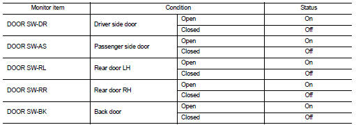
Is the inspection result normal? YES >> Door switch is OK.
NO >> Refer to DLK-87, "Diagnosis Procedure".
Diagnosis Procedure
1.CHECK DOOR SWITCH INPUT SIGNAL
1. Turn ignition switch OFF.
2. Disconnect malfunctioning door switch connector.
3. Check signal between malfunctioning door switch harness connector and ground using oscilloscope.
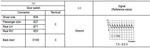
Is the inspection result normal? YES-1 >> Back door: GO TO 3.
YES-2 >> Other door: GO TO 4.
NO >> GO TO 2.
2.CHECK DOOR SWITCH CIRCUIT
1. Disconnect BCM connector.
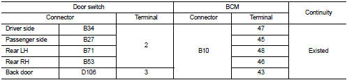
2. Check continuity between door switch harness connector and BCM harness connector.
3. Check continuity between door switch harness connector and ground.
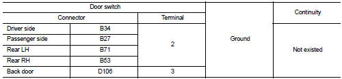
Is the inspection result normal? YES >> Replace BCM. Refer to BCS-93, "Removal and Installation".
NO >> Repair or replace harness.
3.CHECK BACK DOOR SWITCH CIRCUIT
Check continuity between back door lock assembly harness connector and ground.
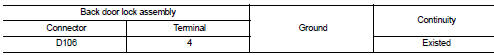
Is the inspection result normal? YES >> GO TO 4.
NO >> Repair or replace harness.
4.CHECK DOOR SWITCH
Refer to DLK-88, "Component Inspection".
Is the inspection result normal? YES >> GO TO 5.
NO >> Replace malfunctioning door switch.
5.CHECK INTERMITTENT INCIDENT
Refer to GI-42, "Intermittent Incident".
>> INSPECTION END
Component Inspection
1.CHECK DOOR SWITCH
1. Turn ignition switch OFF.
2. Disconnect malfunctioning door switch connector.
3. Check continuity between door switch terminals.
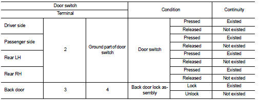
Is the inspection result normal? YES >> INSPECTION END
NO >> Replace malfunction door switch.
 Door request switch
Component Function Check
1.CHECK FUNCTION
1. Select ÔÇťINTELLIGENT KEYÔÇŁ of ÔÇťBCMÔÇŁ using CONSULT-III.
2. Select ÔÇťREQ SW-DRÔÇŁ, ÔÇťREQ SW-ASÔÇŁ in ÔÇťDATA MONITORÔÇŁ mode.
3. Check that the f ...
 Hazard function
Component Function Check
1.CHECK FUNCTION
1. Select ÔÇťINTELLIGENT KEYÔÇŁ of ÔÇťBCMÔÇŁ using CONSULT-III.
2. Select ÔÇťFLASHERÔÇŁ in ÔÇťACTIVE TESTÔÇŁ mode.
3. Check that the function operates nor ...
Other materials:
Turbocharger
Exploded View
1. Heat insulator
2. Actuator hose
3. Clamp
4. Turbocharger inlet tube
5. Gasket
6. Gasket
7. Clamp
8. Oil outlet hose
9. Oil return pipe
10. Oil supply tube
11. O-ring
12. O-ring
13. Turbocharger
14. Eye bolt
15. Gasket
16. Oil supply tube
A. To EVAP canis ...
Connector Information/Explanation of Option Abbreviation
CONNECTOR LIST
Connector information and harness layout are described in ÔÇťPOWER SUPPLY,
GROUND & CIRCUIT ELEMENTSÔÇŁ
Section.
EXPLANATION OF OPTION ABBREVIATION
HOW TO USE CONNECTOR INFORMATION
Description
...
Checking bulbs
With all doors closed, apply the parking brake and place the ignition switch
in the ON position without starting the engine. The following lights will come on:
,
or
,
,
,
,
,
The following lights come on briefly and then go off (if so equipped):
,
or
,
,
,
,
,
,
,
,
,
If ...
