Nissan Juke Service and Repair Manual : Wiring diagram
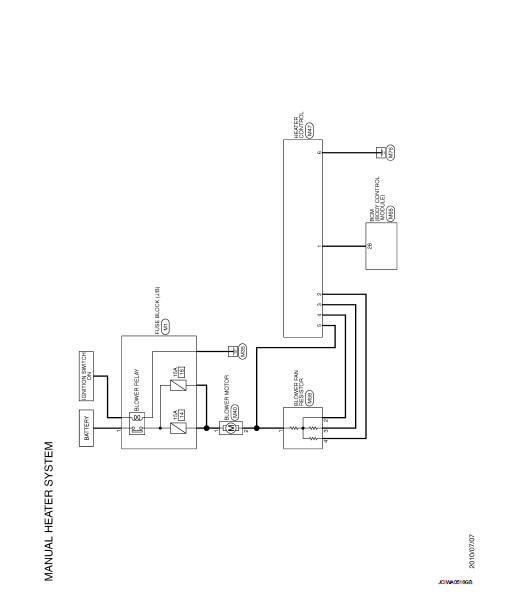
MANUAL HEATER SYSTEM
Wiring Diagram
For connector terminal arrangements, harness layouts, and alphabets in a
 (option abbreviation; if not
described in wiring diagram), refer to GI-12, "Connector Information/Explanation
of Option Abbreviation".
 ECU diagnosis information
BCM
List of ECU Reference
...
 Basic inspection
...
Other materials:
Push-button ignition switch
Removal and Installation
REMOVAL
1. Remove the NATS antenna amp. Refer to SEC-167, "Removal and
Installation".
2. Remove the push-button ignition switch.
1. Disengage the push-button ignition switch fixing pawls
using minus driver etc.
2. Press the push-button ignition switch to ...
Precautions for Drive Shaft
• Observe the following precautions when disassembling and assembling drive
shaft.
- Never disassemble joint sub-assembly because it is non-overhaul parts.
- Perform work in a location which is as dust-free as possible.
- Clean the parts, before disassembling and assembling.
- Prevent the ...
Fusible link inspection
How To Check
A melted fusible link can be detected either by visual inspection or by
feeling with finger tip. If its condition is questionable, use circuit
tester or test lamp.
1 :Fusible link
CAUTION:
• If fusible link should melt, it is possible that critical circuit
(power supply or larg ...
