Nissan Juke Service and Repair Manual : PTC branch line circuit
Diagnosis Procedure
1.CHECK CONNECTOR
1. Turn the ignition switch OFF.
2. Disconnect the battery cable from the negative terminal.
3. Check the terminals and connectors of the PTC heater control unit for damage, bend and loose connection (unit side and connector side).
Is the inspection result normal? YES >> GO TO 2.
NO >> Repair the terminal and connector.
2.CHECK HARNESS FOR OPEN CIRCUIT
1. Disconnect the connector of PTC heater control unit.
2. Check the resistance between the PTC heater control unit harness connector terminals.
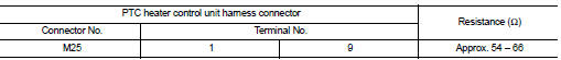
Is the measurement value within the specification? YES >> GO TO 3.
NO >> Repair the PTC heater control unit branch line.
3.CHECK POWER SUPPLY AND GROUND CIRCUIT
Check the power supply and the ground circuit of the PTC heater control unit. Refer to HAC-280, "PTC HEATER CONTROL UNIT : Diagnosis Procedure".
Is the inspection result normal? YES (Present error)>>Replace the PTC heater control unit. Refer to HAC.
YES (Past error)>>Error was detected in the PTC heater control unit branch line.
NO >> Repair the power supply and the ground circuit.
 MDU branch line circuit
Diagnosis Procedure
1.CHECK CONNECTOR
1. Turn the ignition switch OFF.
2. Disconnect the battery cable from the negative terminal.
3. Check the terminals and connectors of the multi display unit f ...
 BCM branch line circuit
Diagnosis Procedure
1.CHECK CONNECTOR
1. Turn the ignition switch OFF.
2. Disconnect the battery cable from the negative terminal.
3. Check the terminals and connectors of the BCM for damage, bend ...
Other materials:
Camshaft valve clearance
Inspection and Adjustment
INSPECTION
Perform inspection as follows after removal, installation or replacement of
camshaft or valve-related parts, or if
there is unusual engine conditions regarding valve clearance.
1. Remove rocker cover. Refer to EM-53, "Exploded View".
2. Measure ...
High pressure fuel pump and fuel hose
Exploded View
CAUTION:
Never remove or disassemble parts unless instructed as shown in the figure.
1. High pressure fuel pump insulator
2. High pressure fuel pump
3. O-ring
4. Valve lifter
5. Fuel tube assembly
6. Bracket
7. Fuel pump connector protector
8. Fuel feed hose
A. To ce ...
Engine stalling
Description
CHART 7: ENGINE STALLING
Diagnosis Procedure
1.CHECK FUEL
Check that the fuel reservoir is correctly filled and with the right fuel.
>> GO TO 2.
2.CHECK ECM POWER SUPPLY AND GROUND CIRCUIT
Check ECM power supply and ground circuit. Refer to EC-885, "Diagnosis
Proc ...
