Nissan Juke Service and Repair Manual : MDU branch line circuit
Diagnosis Procedure
1.CHECK CONNECTOR
1. Turn the ignition switch OFF.
2. Disconnect the battery cable from the negative terminal.
3. Check the terminals and connectors of the multi display unit for damage, bend and loose connection (unit side and connector side).
Is the inspection result normal? YES >> GO TO 2.
NO >> Repair the terminal and connector.
2.CHECK HARNESS FOR OPEN CIRCUIT
1. Disconnect the connector of multi display unit.
2. Check the resistance between the multi display unit harness connector terminals.
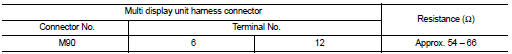
Is the measurement value within the specification? YES >> GO TO 3.
NO >> Repair the multi display unit branch line.
3.CHECK POWER SUPPLY AND GROUND CIRCUIT
Check the power supply and the ground circuit of the multi display unit. Refer to AV-123, "MULTI DISPLAY UNIT : Diagnosis Procedure".
Is the inspection result normal? YES (Present error)>>Replace the multi display unit. Refer to DMS-13, "Removal and Installation".
YES (Past error)>>Error was detected in the multi display unit branch line.
NO >> Repair the power supply and the ground circuit.
 HVAC branch line circuit
Diagnosis Procedure
1.CHECK CONNECTOR
1. Turn the ignition switch OFF.
2. Disconnect the battery cable from the negative terminal.
3. Check the terminals and connectors of the A/C auto amp. for da ...
 PTC branch line circuit
Diagnosis Procedure
1.CHECK CONNECTOR
1. Turn the ignition switch OFF.
2. Disconnect the battery cable from the negative terminal.
3. Check the terminals and connectors of the PTC heater control u ...
Other materials:
P1078 EVT control position sensor
DTC Logic
DTC DETECTION LOGIC
DTC CONFIRMATION PROCEDURE
1.PRECONDITIONING
If DTC Confirmation Procedure has been previously conducted, always perform
the following procedure
before conducting the next test.
1. Turn ignition switch OFF and wait at least 10 seconds.
2. Turn ignition swit ...
Additional service when removing battery negative terminal
Description
When the battery negative terminal is disconnected, the initialization is
necessary for normal operation of
power window system.
CAUTION:
The following specified operations can not be performed under the
non-initialized condition.
• Auto-up operation
• Anti-pinch function ...
Parts Requiring Angle Tightening
• Use the angle wrench [SST: KV10112100] for the final tightening of the
following engine parts:
- Cylinder head bolts
- Lower cylinder block bolts
- Connecting rod cap bolts
- Crankshaft pulley bolt (No the angle wrench is required as bolt flange is
provided with notches for angle
tighte ...
