Nissan Juke Service and Repair Manual : HVAC branch line circuit
Diagnosis Procedure
1.CHECK CONNECTOR
1. Turn the ignition switch OFF.
2. Disconnect the battery cable from the negative terminal.
3. Check the terminals and connectors of the A/C auto amp. for damage, bend and loose connection (unit side and connector side).
Is the inspection result normal? YES >> GO TO 2.
NO >> Repair the terminal and connector.
2.CHECK HARNESS FOR OPEN CIRCUIT
1. Disconnect the connector of A/C auto amp.
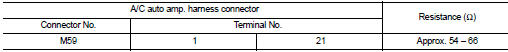
2. Check the resistance between the A/C auto amp. harness connector terminals.
- 4WD models
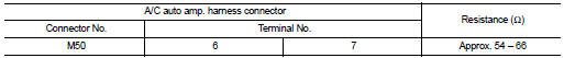
- 2WD models
Is the measurement value within the specification? YES >> GO TO 3.
NO >> Repair the A/C auto amp. branch line.
3.CHECK POWER SUPPLY AND GROUND CIRCUIT
Check the power supply and the ground circuit of the A/C auto amp. Refer to the following.
• 4WD models: HAC-73, "A/C AUTO AMP. : Diagnosis Procedure" • 2WD models: HAC-162, "A/C AUTO AMP. : Diagnosis Procedure"
Is the inspection result normal? YES (Present error)>>Replace the A/C auto amp. Refer to the following.
• 4WD models: HAC-91, "Removal and Installation" • 2WD models: HAC-188, "Removal and Installation"
YES (Past error)>>Error was detected in the A/C auto amp. branch line.
NO >> Repair the power supply and the ground circuit.
 A-bag branch line circuit
Diagnosis Procedure
WARNING:
• Before servicing, turn ignition switch OFF, disconnect battery negative
terminal, and wait 3 minutes
or more. (To discharge backup capacitor.)
• Never use unsp ...
 MDU branch line circuit
Diagnosis Procedure
1.CHECK CONNECTOR
1. Turn the ignition switch OFF.
2. Disconnect the battery cable from the negative terminal.
3. Check the terminals and connectors of the multi display unit f ...
Other materials:
B2321, B2322 oil level sensor
Description
The oil level sensor detects the level of engine oil, and then transmits the
oil level signal to the combination
meter.
DTC Logic
DTC DETECTION LOGIC
NOTE:
When the following conditions are satisfied, the combination meter reads the
resistance value of oil level sensor.
Th ...
B1036 crash zone sensor
DTC Logic
DTC DETECTION LOGIC
DTC CONFIRMATION PROCEDURE
1.CHECK SELF-DIAG RESULT
With CONSULT-III
1. Turn ignition switch ON.
2. Perform “Self Diagnostic Result” mode of “AIR BAG” using CONSULT-III.
Without CONSULT-III
1. Turn ignition switch ON.
2. Check the air bag warning la ...
P0488 EGR system
DTC Logic
DTC DETECTION LOGIC
Diagnosis Procedure
1.CHECK EGR VOLUME CONTROL VALVE CONTROL CIRCUIT
1. Turn ignition switch OFF.
2. Disconnect EGR volume control valve harness connector and ECM harness
connector.
3. Check the continuity between EGR volume control valve terminal harness
co ...
